Lexus ES: Installation
INSTALLATION
PROCEDURE
1. INSTALL TELEPHONE AND GPS ANTENNA BRACKET
2. INSTALL TELEPHONE AND GPS ANTENNA ASSEMBLY
(a) Engage the 6 guides and 2 claws to install the telephone and GPS antenna assembly as shown in the illustration.
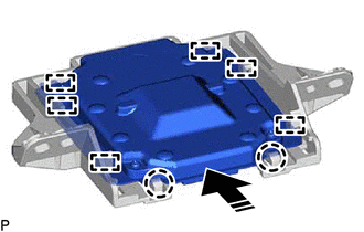
.png) | Install in this Direction |
3. INSTALL TELEPHONE AND GPS ANTENNA ASSEMBLY WITH BRACKET
(a) Install the telephone and GPS antenna assembly with bracket with the 2 screws.
(b) Engage the 2 claws.
(c) Connect the connector.
4. INSTALL NO. 3 HEATER TO REGISTER DUCT
Click here .gif)
5. INSTALL DEFROSTER NOZZLE ASSEMBLY
Click here
6. INSTALL NO. 2 SIDE DEFROSTER NOZZLE DUCT
Click here
7. INSTALL INSTRUMENT PANEL SAFETY PAD SUB-ASSEMBLY
Click here
READ NEXT:
 Removal
REMOVAL CAUTION / NOTICE / HINT The necessary procedures (adjustment, calibration, initialization, or registration) that must be performed after parts are removed and installed, or replaced during tel
Components
COMPONENTS ILLUSTRATION *1 TELEPHONE AND GPS ANTENNA CORD - -
SEE MORE:
Lost Communication with Body Control Module "B" Missing Message (U014287,U015587,U020887)
DESCRIPTION The multiplex tilt and telescopic ECU receives signals from the main body ECU (multiplex network body ECU), combination meter assembly and position control ECU assembly (driver seat) via CAN communication. DTC No. Detection Item DTC Detection Condition Trouble Area U014287
Internal Control Module Software Incompatibility Not Programmed (U030051)
DESCRIPTION The forward recognition camera receives vehicle information from the ECM via CAN communication. DTC U030051 is stored when the vehicle information from the ECM cannot be confirmed. DTC No. Detection Item DTC Detection Condition Trouble Area U030051 Internal Control Module
© 2016-2026 Copyright www.lexguide.net
