Lexus ES: Components
Lexus ES (XZ10) Service Manual / Vehicle Interior / Mirror (ext) / Outer Rear View Mirror Cover / Components
COMPONENTS
ILLUSTRATION
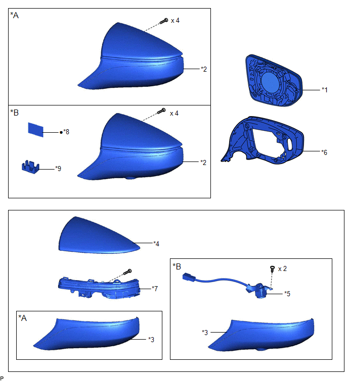
| *A | w/o Panoramic View Monitor System | *B | w/ Panoramic View Monitor System |
| *1 | OUTER MIRROR | *2 | OUTER MIRROR COVER ASSEMBLY |
| *3 | OUTER MIRROR LOWER COVER | *4 | OUTER MIRROR UPPER COVER |
| *5 | SIDE TELEVISION CAMERA ASSEMBLY | *6 | VISOR COVER ASSEMBLY |
| *7 | SIDE TURN SIGNAL LIGHT ASSEMBLY | *8 | OUTER MIRROR TAPE |
| *9 | CAMERA CONNECTOR CLAMP | - | - |
| ● | Non-reusable part | - | - |
READ NEXT:
 Removal
REMOVAL CAUTION / NOTICE / HINT The necessary procedures (adjustment, calibration, initialization, or registration) that must be performed after parts are removed and installed, or replaced during out
Installation
INSTALLATION CAUTION / NOTICE / HINT HINT:
Use the same procedure for the RH side and LH side.
The following procedure is for the LH side.
PROCEDURE 1. INSTALL VISOR COVER ASSEMBLY (a) Install
SEE MORE:
Inspection
INSPECTION PROCEDURE 1. INSPECT CANISTER (CHARCOAL CANISTER ASSEMBLY) (a) Visually check the canister (charcoal canister assembly). (1) Visually check the canister (charcoal canister assembly) for cracks or damage. If cracks or damage are found, replace the canister (charcoal canister assembly).
Components
COMPONENTS ILLUSTRATION *A except 2GR-FKS - - *1 KICK DOOR CONTROL SENSOR *2 KICK DOOR CONTROL SENSOR WITH BRACKET *3 KICK DOOR CONTROL BRACKET - - ILLUSTRATION *A for 2GR-FKS - - *1 KICK DOOR CONTROL SENSOR *2 KICK DOOR CONTROL SENSOR WITH BRACKE
© 2016-2026 Copyright www.lexguide.net
