Lexus ES: Left Front Wheel Speed Sensor Circuit Short to Battery (C050012)
DESCRIPTION
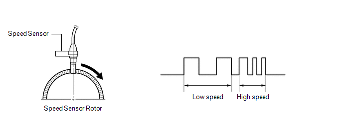
Each speed sensor detects wheel speed and sends signals to the skid control ECU (brake actuator assembly). These signals are used by the ABS control.
The speed sensor detects the magnetic fields of the speed sensor rotor as it rotates and outputs a pulse signal.
The frequency of the pulse varies in accordance with the rotational speed of the speed sensor rotor and the system uses this to determine the wheel speed.
HINT:
The following example shows a pulse signal that is output when the wire harness connectors are connected to the speed sensors and skid control ECU (brake actuator assembly).
| DTC No. | Detection Item | DTC Detection Condition | Trouble Area |
|---|---|---|---|
| C050012 | Left Front Wheel Speed Sensor Circuit Short to Battery | A short to +B in the speed sensor signal circuit is detected for 0.12 seconds or more. |
|
*: w/ AVS
WIRING DIAGRAM
w/o AVS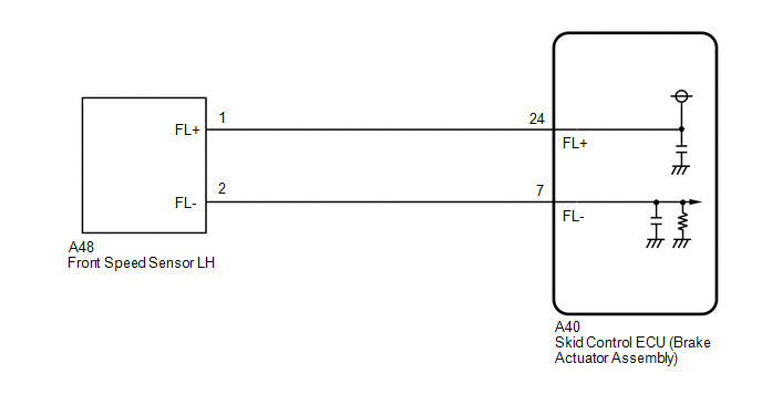 w/ AVS
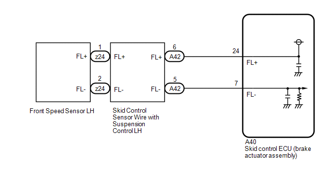
CAUTION / NOTICE / HINT
NOTICE:
-
After replacing the skid control ECU (brake actuator assembly), perform acceleration sensor zero point calibration and store system information memorization.
Click here
.gif)
-
After replacing or removing and installing a speed sensor, perform Dealer Mode (Signal Check) inspection to confirm that the speed sensors are operating correctly.
Click here
PROCEDURE
| 1. | CHECK VEHICLE |
(a) Check if the vehicle is equipped with AVS.
| Result | Proceed to |
|---|---|
| w/o AVS | A |
| w/ AVS | B |
| B |  | GO TO STEP 5 |
|

| 2. | CHECK HARNESS AND CONNECTOR (SENSOR GROUND CIRCUIT) |
| (a) Make sure that there is no looseness at the locking part and the connecting part of the connectors. OK: The connector is securely connected. |
|
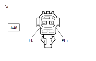
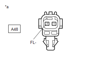
(b) Disconnect the A48 front speed sensor LH connector.
(c) Check both the connector case and the terminals for deformation and corrosion.
OK:
No deformation or corrosion.
(d) Turn the engine switch on (IG).
(e) Measure the voltage according to the value(s) in the table below.
Standard Voltage:
| Tester Connection | Condition | Specified Condition |
|---|---|---|
| A48-1 (FL+) - A48-2 (FL-) | Engine switch on (IG) | 11 to 14 V |
| OK | | REPLACE FRONT SPEED SENSOR LH |
|
| 3. | CHECK HARNESS AND CONNECTOR (FRONT SPEED SENSOR LH - BRAKE ACTUATOR ASSEMBLY) |
| (a) Make sure that there is no looseness at the locking part and the connecting part of the connectors. OK: The connector is securely connected. |
|
(b) Disconnect the A40 skid control ECU (brake actuator assembly) connector.
(c) Disconnect the A48 front speed sensor LH connector.
(d) Check both the connector case and the terminals for deformation and corrosion.
OK:
No deformation or corrosion.
(e) Measure the voltage according to the value(s) in the table below.
Standard Voltage:
| Tester Connection | Condition | Specified Condition |
|---|---|---|
| A48-2 (FL-) - Body ground | Always | Below 1.5 V |
| NG | | REPAIR OR REPLACE HARNESS OR CONNECTOR |
|
| 4. | CHECK HARNESS AND CONNECTOR (FRONT SPEED SENSOR LH - BRAKE ACTUATOR ASSEMBLY) |
(a) Make sure that there is no looseness at the locking part and the connecting part of the connectors.
OK:
The connector is securely connected.
(b) Disconnect the A40 skid control ECU (brake actuator assembly) connector.
(c) Disconnect the A48 front speed sensor LH connector.
(d) Check both the connector case and the terminals for deformation and corrosion.
OK:
No deformation or corrosion.
(e) Measure the resistance according to the value(s) in the table below.
Standard Resistance:
| Tester Connection | Condition | Specified Condition |
|---|---|---|
| A48-1 (FL+) or A40-24 (FL+) - A48-2 (FL-) or A40-7 (FL-) | Always | 10 kΩ or higher |
| OK | | REPLACE BRAKE ACTUATOR ASSEMBLY |
| NG | | REPAIR OR REPLACE HARNESS OR CONNECTOR |
| 5. | CHECK HARNESS AND CONNECTOR (SENSOR GROUND CIRCUIT) |
| (a) Make sure that there is no looseness at the locking part and the connecting part of the connectors. OK: The connector is securely connected. |
|
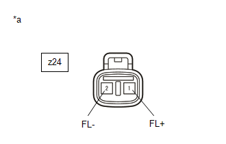
(b) Disconnect the z24 front speed sensor LH connector.
(c) Check both the connector case and the terminals for deformation and corrosion.
OK:
No deformation or corrosion.
(d) Turn the engine switch on (IG).
(e) Measure the voltage according to the value(s) in the table below.
Standard Voltage:
| Tester Connection | Condition | Specified Condition |
|---|---|---|
| z24-1 (FL+) - z24-2 (FL-) | Engine switch on (IG) | 11 to 14 V |
| OK | | REPLACE FRONT SPEED SENSOR LH |
|
| 6. | CHECK HARNESS AND CONNECTOR (SENSOR GROUND CIRCUIT) |
| (a) Make sure that there is no looseness at the locking part and the connecting part of the connectors. OK: The connector is securely connected. |
|
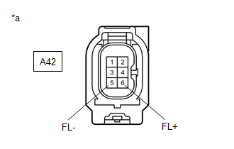
(b) Disconnect the A42 skid control sensor wire with suspension control LH connector.
(c) Check both the connector case and the terminals for deformation and corrosion.
OK:
No deformation or corrosion.
(d) Turn the engine switch on (IG).
(e) Measure the voltage according to the value(s) in the table below.
Standard Voltage:
| Tester Connection | Condition | Specified Condition |
|---|---|---|
| A42-6 (FL+) - A42-5 (FL-) | Engine switch on (IG) | 11 to 14 V |
| OK | | REPLACE SKID CONTROL SENSOR WIRE WITH SUSPENSION CONTROL LH |
|
| 7. | CHECK HARNESS AND CONNECTOR (SKID CONTROL SENSOR WIRE WITH SUSPENSION CONTROL LH - BRAKE ACTUATOR ASSEMBLY) |
| (a) Make sure that there is no looseness at the locking part and the connecting part of the connectors. OK: The connector is securely connected. |
|
(b) Disconnect the A40 skid control ECU (brake actuator assembly) connector.
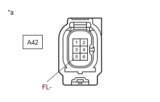
(c) Disconnect the A42 skid control sensor wire with suspension control LH connector.
(d) Check both the connector case and the terminals for deformation and corrosion.
OK:
No deformation or corrosion.
(e) Measure the voltage according to the value(s) in the table below.
Standard Voltage:
| Tester Connection | Condition | Specified Condition |
|---|---|---|
| A42-5 (FL-) - Body ground | Always | Below 1.5 V |
| NG | | REPAIR OR REPLACE HARNESS OR CONNECTOR |
|
| 8. | CHECK HARNESS AND CONNECTOR (SKID CONTROL SENSOR WIRE WITH SUSPENSION CONTROL LH - BRAKE ACTUATOR ASSEMBLY) |
(a) Make sure that there is no looseness at the locking part and the connecting part of the connectors.
OK:
The connector is securely connected.
(b) Disconnect the A40 skid control ECU (brake actuator assembly) connector.
(c) Disconnect the A42 skid control sensor wire with suspension control LH connector.
(d) Check both the connector case and the terminals for deformation and corrosion.
OK:
No deformation or corrosion.
(e) Measure the resistance according to the value(s) in the table below.
Standard Resistance:
| Tester Connection | Condition | Specified Condition |
|---|---|---|
| A42-6 (FL+) or A40-24 (FL+) - A42-5 (FL-) or A40-7 (FL-) | Always | 10 kΩ or higher |
| OK | | REPLACE BRAKE ACTUATOR ASSEMBLY |
| NG | | REPAIR OR REPLACE HARNESS OR CONNECTOR |
READ NEXT:
 Left Front Wheel Speed Sensor Circuit Short to Ground or Open (C050014)
DESCRIPTION Refer to DTC C050012 Click here DTC No. Detection Item DTC Detection Condition Trouble Area C050014 Left Front Wheel Speed Sensor Circuit Short to Ground or Open A short
Left Front Wheel Speed Sensor Signal Stuck Low (C050023)
DESCRIPTION Refer to DTC C050012 Click here DTC No. Detection Item DTC Detection Condition Trouble Area C050023 Left Front Wheel Speed Sensor Signal Stuck Low
When the vehicle is
Left Front Wheel Speed Sensor Signal Stuck High (C050024)
DESCRIPTION Refer to DTC C050012 Click here DTC No. Detection Item DTC Detection Condition Trouble Area C050024 Left Front Wheel Speed Sensor Signal Stuck High The speed sensor sign
SEE MORE:
Rear Power Window RH Auto Up / Down Function does not Operate with Rear Power Window Switch RH
DESCRIPTION If the manual up and down functions operate normally but the auto up and down functions do not, the power window control system may be in fail-safe mode. If power window initialization has not been performed, the auto up and down functions will not operate. Click here WIRING DIAGRAM C
Abnormal Leak in Accumulator (C1391)
DESCRIPTION This DTC is stored if internal or external brake fluid leaks are detected due to improper sealing in the brake actuator (brake booster with master cylinder assembly) or brake booster pump assembly. Internal leaks are suspected if the pump motor operates frequently without braking. DTC
