Lexus ES: Inspection
INSPECTION
PROCEDURE
1. INSPECT HAZARD WARNING SIGNAL SWITCH ASSEMBLY
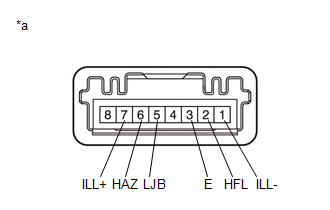
| *a | Component without harness connected (Hazard Warning Signal Switch Assembly) |
(a) Measure the resistance according to the value(s) in the table below.
Standard Resistance:
| Tester Connection | Condition | Specified Condition |
|---|---|---|
| 6 (HAZ) - 3 (E) | Hazard warning switch off | 10 kΩ or higher |
| Hazard warning switch on | Below 1 Ω |
If the result is not as specified, replace the hazard warning signal switch assembly.
(b) Apply auxiliary battery voltage to the hazard warning signal switch assembly and check that the switch illuminates.
OK:
Switch Illumination| Measurement Condition | Condition | Specified Condition |
|---|---|---|
| Auxiliary battery positive (+) → Terminal 7 (ILL+) Auxiliary battery negative (-) → Terminal 1 (ILL-) | Always | Switch illumination illuminates |
OK:
Switch Indicator| Measurement Condition | Condition | Specified Condition |
|---|---|---|
| Auxiliary battery positive (+) → Terminal 2 (HFL) Auxiliary battery negative (-) → Terminal 5 (LJB) | Always | Switch indicator illuminates |
If the result is not as specified, replace the hazard warning signal switch assembly.
READ NEXT:
 Installation
INSTALLATION PROCEDURE 1. INSTALL HAZARD WARNING SIGNAL SWITCH ASSEMBLY (a) Engage the 2 claws to install the hazard warning signal switch assembly. Install in this Direction 2. INSTALL NO.
Components
COMPONENTS ILLUSTRATION *1 COWL TOP PANEL INSULATOR *2 FRONT FENDER SPLASH SHIELD SUB-ASSEMBLY *3 HEADLIGHT ASSEMBLY - - N*m (kgf*cm, ft.*lbf): Specified torque - - I
SEE MORE:
Brake Pressure Control Solenoid "C" Control Circuit Short to Battery (C14F112,...,C14F149)
DESCRIPTION The ABS solenoid relay and reservoir cut solenoid valves are built into the brake actuator assembly. When the brakes are operating, the reservoir cut solenoid valves supply brake fluid from the brake master cylinder reservoir assembly to the pump motor as necessary. When this DTC is stor
Brake Hold Standby Indicator Light Circuit
DESCRIPTION The brake hold standby indicator light turns on if brake hold control is possible when the following conditions required for operation standby are met and the brake hold switch (No. 3 combination switch assembly) is turned on while the power switch is on (IG).
Conditions required for
