Lexus ES: Components
COMPONENTS
ILLUSTRATION
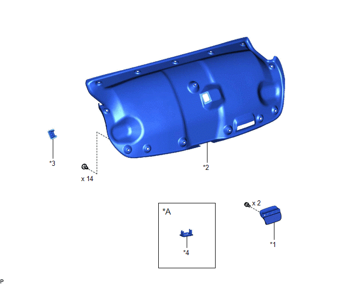
| *A | w/ Power Trunk Lid System | - | - |
| *1 | LUGGAGE COMPARTMENT DOOR ASSIST GRIP | *2 | LUGGAGE COMPARTMENT DOOR COVER |
| *3 | LUGGAGE LOCK CONTROL CABLE PLATE | *4 | SWITCH BEZEL |
ILLUSTRATION
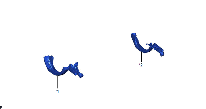
| *1 | LUGGAGE COMPARTMENT DOOR HINGE COVER LH | *2 | LUGGAGE COMPARTMENT DOOR HINGE COVER RH |
ILLUSTRATION
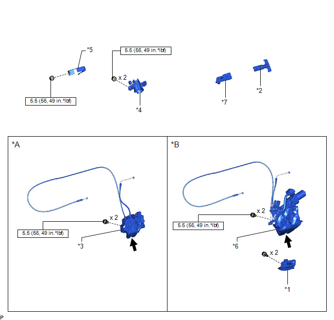
| *A | w/o Power Trunk Lid System | *B | w/ Power Trunk Lid System |
| *1 | DOOR CONTROL SWITCH | *2 | LUGGAGE COMPARTMENT DOOR INSIDE HANDLE |
| *3 | LUGGAGE COMPARTMENT DOOR LOCK ASSEMBLY | *4 | LUGGAGE COMPARTMENT DOOR LOCK CYLINDER ASSEMBLY |
| *5 | LUGGAGE COMPARTMENT KEY CYLINDER PROTECTOR | *6 | LUGGAGE DOOR CLOSER ASSEMBLY |
| *7 | LUGGAGE LOCK CONTROL CABLE CLAMP | - | - |
.png) | N*m (kgf*cm, ft.*lbf): Specified torque | .png) | MP grease |
ILLUSTRATION
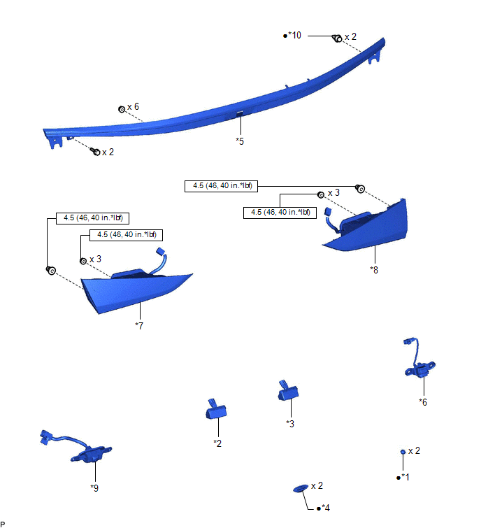
| *1 | HOLE PLUG | *2 | LICENSE PLATE LIGHT ASSEMBLY LH |
| *3 | LICENSE PLATE LIGHT ASSEMBLY RH | *4 | LUGGAGE COMPARTMENT DOOR CUSHION |
| *5 | LUGGAGE COMPARTMENT DOOR OUTSIDE GARNISH SUB-ASSEMBLY | *6 | LUGGAGE ELECTRICAL KEY SWITCH |
| *7 | REAR LIGHT ASSEMBLY LH | *8 | REAR LIGHT ASSEMBLY RH |
| *9 | TELEVISION CAMERA ASSEMBLY WITH WIRE | *10 | CLIP |
| | N*m (kgf*cm, ft.*lbf): Specified torque | ● | Non-reusable part |
ILLUSTRATION
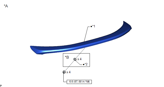
| *A | w/ Rear Spoiler | *B | for TMMK Made |
| *1 | REAR SPOILER SUB-ASSEMBLY | *2 | GASKET |
| | N*m (kgf*cm, ft.*lbf): Specified torque | ● | Non-reusable part |
READ NEXT:
 Disassembly
DISASSEMBLY CAUTION / NOTICE / HINT The necessary procedures (adjustment, calibration, initialization, or registration) that must be performed after parts are removed and installed, or replaced during
Adjustment
ADJUSTMENT CAUTION / NOTICE / HINT *a Centering Bolt *b Standard Bolt HINT:
Centering bolts are used to mount the door hinge to the door. The door cannot be adjusted with the centeri
Reassembly
REASSEMBLY PROCEDURE 1. INSTALL REAR SPOILER SUB-ASSEMBLY (w/ Rear Spoiler) Click here 2. INSTALL LICENSE PLATE LIGHT ASSEMBLY LH Click here 3. INSTALL LICENSE PLATE LIGHT ASSEMBLY RH HINT: Use th
SEE MORE:
Torque Converter Clutch Actuator Stuck On (P07407E)
DESCRIPTION The ECM uses signals from the throttle position sensor, mass air flow meter, transmission revolution sensor (NT), transmission revolution sensor (NC) and crankshaft position sensor to help determine the engagement timing of the lock-up clutch. The ECM monitors the engagement of the clutc
Components
COMPONENTS ILLUSTRATION *1 BATTERY SERVICE HOLE COVER *2 SERVICE PLUG GRIP ILLUSTRATION *1 CONNECTOR COVER ASSEMBLY *2 ENGINE ROOM MAIN WIRE Tightening torque for "Major areas involving basic vehicle performance such as moving/turning/stopping": N*m (kgf*cm, ft.*lbf)
