Lexus ES: Adjustment
ADJUSTMENT
CAUTION / NOTICE / HINT
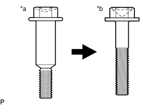
| *a | Centering Bolt |
| *b | Standard Bolt |
HINT:
- Centering bolts are used to mount the door hinge to the door. The door cannot be adjusted with the centering bolts installed. Substitute the centering bolts with standard bolts when making adjustments.
-
Specified torque for standard bolts is shown in the standard bolt chart.
Click here
.gif)
PROCEDURE
1. INSPECT LUGGAGE COMPARTMENT DOOR
(a) Check that the clearance measurements of areas a through e are within each standard range.
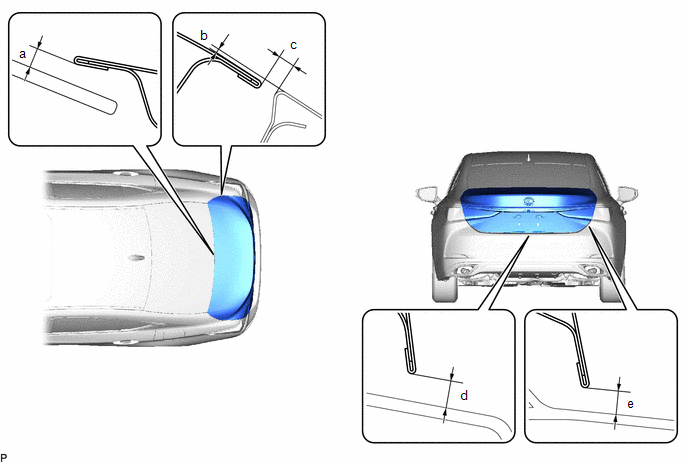 Standard Clearance
 | Area | Measurement | Area | Measurement |
|---|---|---|---|
| a | 5.05 mm (0.199 in.) | b | -0.8 to 2.2 mm (-0.0315 to 0.0866 in.) |
| c | 2.0 to 5.0 mm (0.0787 to 0.197 in.) | d | 3.2 to 5.9 mm (0.126 to 0.232 in.) |
| e | 3.2 to 5.9 mm (0.126 to 0.232 in.) | - | - |
2. REMOVE LUGGAGE COMPARTMENT FLOOR MAT
Click here
3. REMOVE SPARE WHEEL COVER TRAY
Click here
4. REMOVE REAR FLOOR FINISH PLATE
Click here
5. REMOVE LUGGAGE LOCK CONTROL CABLE PLATE
Click here
6. REMOVE SWITCH BEZEL (w/ Power Trunk Lid System)
Click here
7. REMOVE LUGGAGE COMPARTMENT DOOR COVER
Click here
8. REMOVE LUGGAGE COMPARTMENT DOOR HINGE COVER LH
Click here
9. REMOVE LUGGAGE COMPARTMENT DOOR HINGE COVER RH
HINT:
Use the same procedure as for the LH side.
10. ADJUST LUGGAGE COMPARTMENT DOOR
| (a) Loosen the 4 door side hinge bolts to adjust the door horizontally and vertically. |
|
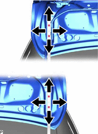
(b) Tighten the 4 bolts after adjustment.
Torque:
7.0 N·m {71 kgf·cm, 62 in·lbf}
| (c) Using a T40 "TORX" socket wrench, slightly loosen the 2 striker mounting screws. |
|
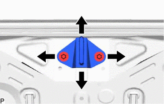
(d) Using a brass bar and a hammer, hit the striker to adjust its position.
(e) Using a T40 "TORX" socket wrench, tighten the 2 striker mounting screws after adjustment.
Torque:
23 N·m {235 kgf·cm, 17 ft·lbf}
11. INSTALL LUGGAGE COMPARTMENT DOOR HINGE COVER LH
Click here
12. INSTALL LUGGAGE COMPARTMENT DOOR HINGE COVER RH
HINT:
Use the same procedure as for the LH side.
13. INSTALL LUGGAGE COMPARTMENT DOOR COVER
Click here
14. INSTALL SWITCH BEZEL (w/ Power Trunk Lid System)
Click here
15. INSTALL LUGGAGE LOCK CONTROL CABLE PLATE
Click here
16. INSTALL REAR FLOOR FINISH PLATE
Click here
17. INSTALL SPARE WHEEL COVER TRAY
Click here
18. INSTALL LUGGAGE COMPARTMENT FLOOR MAT
Click here
READ NEXT:
 Reassembly
REASSEMBLY PROCEDURE 1. INSTALL REAR SPOILER SUB-ASSEMBLY (w/ Rear Spoiler) Click here 2. INSTALL LICENSE PLATE LIGHT ASSEMBLY LH Click here 3. INSTALL LICENSE PLATE LIGHT ASSEMBLY RH HINT: Use th
Luggage Compartment Door Closer Switch
ComponentsCOMPONENTS ILLUSTRATION *1 DOOR CONTROL SWITCH *2 LUGGAGE COMPARTMENT DOOR COVER *3 LUGGAGE LOCK CONTROL CABLE PLATE *4 SWITCH BEZEL RemovalREMOVAL PROCEDURE 1. REMO
SEE MORE:
Reverse Shift-linked Function of Power Mirrors does not Operate
DESCRIPTION The ECM sends the reverse signal to the main body ECU (multiplex network body ECU) via CAN communication. When receiving the reverse signal, the main body ECU (multiplex network body ECU) sends the reverse request signal to each outer mirror control ECU assembly. Based on the signal, eac
Removal
REMOVAL CAUTION / NOTICE / HINT The necessary procedures (adjustment, calibration, initialization or registration) that must be performed after parts are removed and installed, or replaced during steering column assembly removal/installation are shown below. Necessary Procedures After Parts Removed/
