Lexus ES: Installation
INSTALLATION
CAUTION / NOTICE / HINT
HINT:
- Use the same procedure for the RH side and LH side.
- The following procedure is for the LH side.
PROCEDURE
1. INSTALL HOOD SUPPORT BRACKET
(a) Engage the guide.
(b) Install the hood support bracket with the bolt.
Torque:
17.5 N·m {178 kgf·cm, 13 ft·lbf}
2. INSTALL FRONT FENDER SPLASH SHIELD SUB-ASSEMBLY
(a) Engage the 2 guides as shown in the illustration.
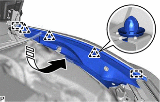
.png) | Install in this Direction |
(b) Engage the 3 clips to install the front fender splash shield sub-assembly.
3. INSTALL NO. 3 COWL TOP PANEL INSULATOR
Click here .gif)
4. INSTALL COOL AIR INTAKE DUCT SEAL
Click here
5. INSTALL HOOD STAY BRACKET
(a) Engage the guide.
(b) Install the hood stay bracket with the bolt.
Torque:
17.5 N·m {178 kgf·cm, 13 ft·lbf}
6. INSTALL HOOD SUPPORT ASSEMBLY
NOTICE:
- Avoid touching the piston rod as much as possible to prevent foreign matter from attaching to it. Be sure to hold the cylinder while servicing.
- Do not wear cotton gloves or other similar materials when handling the piston rod. Fibers may attach to the rod and result in gas leaks.
- Do not apply any horizontal load to the hood support assembly in order to prevent the piston rod from deforming.
| (a) Engage the 2 ball joints to install the hood support assembly. NOTICE: Install the hood support assembly while supporting the hood by hand. |
|
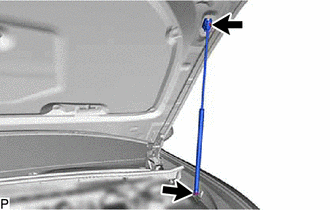
(b) Check that the ball joints are engaged securely and the hood support assembly cannot be pulled off.
READ NEXT:
 Disposal
DISPOSAL PROCEDURE 1. DISPOSE OF HOOD SUPPORT ASSEMBLY (a) Secure the hood support assembly horizontally in a vise with the piston rod pulled out. (b) Wearing safety glasses, gradually cut a part w
Components
COMPONENTS ILLUSTRATION *A except 2GR-FKS - - *1 KICK DOOR CONTROL SENSOR *2 KICK DOOR CONTROL SENSOR WITH BRACKET *3 KICK DOOR CONTROL BRACKET - - ILLUSTRATION *A
SEE MORE:
Diagnostic Trouble Code Chart
DIAGNOSTIC TROUBLE CODE CHART Vehicle Proximity Notification System DTC No. Detection Item Link B1350 Speaker Circuit U0129 Lost Communication with Brake System Control Module U0140 Lost Communication with Body Control Module U0293 Lost Communication wit
Reassembly
REASSEMBLY PROCEDURE 1. INSTALL GENERATOR ROTOR BEARING (a) Using SST and a press, install a new generator rotor bearing. SST: 09950-60011 09951-00470 SST: 09950-70010 09951-07100 (b) Fit the tabs of the retainer plate into the cutouts of the generator drive end frame to install th
