Lexus ES: Removal
REMOVAL
CAUTION / NOTICE / HINT
HINT:
- Use the same procedure for the RH side and LH side.
- The following procedure is for the LH side.
PROCEDURE
1. REMOVE HOOD SUPPORT ASSEMBLY
NOTICE:
- Avoid touching the piston rod as much as possible to prevent foreign matter from attaching to it. Be sure to hold the cylinder while servicing.
- Do not wear cotton gloves or other similar materials when handling the piston rod. Fibers may attach to the rod and result in gas leaks.
- Do not apply any horizontal load to the hood support assembly in order to prevent the piston rod from deforming.
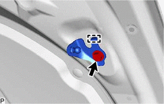
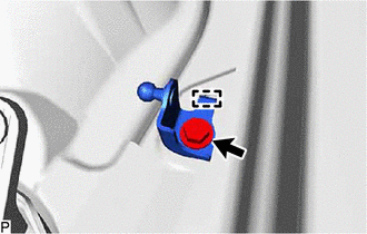
| (a) Using a screwdriver with its tip wrapped with protective tape, slightly raise the 2 stop rings as shown in the illustration. NOTICE:
|
|

(b) Disengage the 2 ball joints to remove the hood support assembly.
NOTICE:
Remove the hood support assembly while supporting the hood sub-assembly by hand.
2. REMOVE HOOD STAY BRACKET
| (a) Remove the bolt. |
|
(b) Disengage the guide to remove the hood stay bracket.
3. REMOVE COOL AIR INTAKE DUCT SEAL
Click here .gif)
4. REMOVE NO. 3 COWL TOP PANEL INSULATOR
Click here
5. REMOVE FRONT FENDER SPLASH SHIELD SUB-ASSEMBLY
(a) Disengage the 3 clips.

.png) | Remove in this Direction |
(b) Disengage the 2 guides and remove the front fender splash shield sub-assembly as shown in the illustration.
6. REMOVE HOOD SUPPORT BRACKET
| (a) Remove the bolt. |
|
(b) Disengage the guide to remove the hood support bracket.
READ NEXT:
 Installation
INSTALLATION CAUTION / NOTICE / HINT HINT:
Use the same procedure for the RH side and LH side.
The following procedure is for the LH side.
PROCEDURE 1. INSTALL HOOD SUPPORT BRACKET (a) Engage
Disposal
DISPOSAL PROCEDURE 1. DISPOSE OF HOOD SUPPORT ASSEMBLY (a) Secure the hood support assembly horizontally in a vise with the piston rod pulled out. (b) Wearing safety glasses, gradually cut a part w
SEE MORE:
Removal
REMOVAL CAUTION / NOTICE / HINT The necessary procedures (adjustment, calibration, initialization or registration) that must be performed after parts are removed and installed, or replaced during fuel pressure sensor removal/installation are shown below. Necessary Procedures After Parts Removed/Inst
Problem Symptoms Table
PROBLEM SYMPTOMS TABLE NOTICE:
Before performing troubleshooting, change the grille shutter control mode to maintenance mode.
Click here
If the swing grille actuator assembly has been replaced with a new one, perform initialization and change the grille shutter control mode.
Click here
