Lexus ES: Components
Lexus ES (XZ10) Service Manual / Vehicle Interior / Door / Hatch / Fuel Lid Opener Motor Assembly / Components
COMPONENTS
ILLUSTRATION
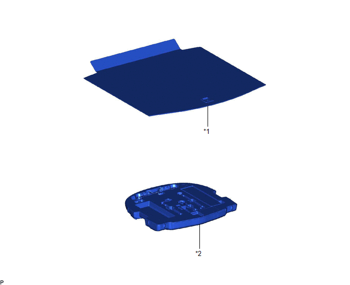
| *1 | LUGGAGE COMPARTMENT FLOOR MAT | *2 | SPARE WHEEL COVER TRAY |
ILLUSTRATION
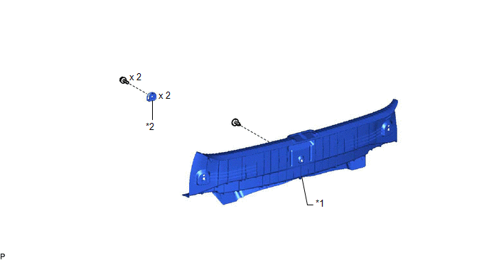
| *1 | REAR FLOOR FINISH PLATE | *2 | LUGGAGE HOLD BELT STRIKER ASSEMBLY |
ILLUSTRATION
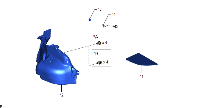
| *A | for Type A | *B | for Type B |
| *1 | LUGGAGE COMPARTMENT TRIM COVER LH | *2 | LUGGAGE COMPARTMENT TRIM INNER COVER LH |
| *3 | ROPE HOOK | *4 | LUGGAGE HOLD BELT STRIKER ASSEMBLY |
ILLUSTRATION
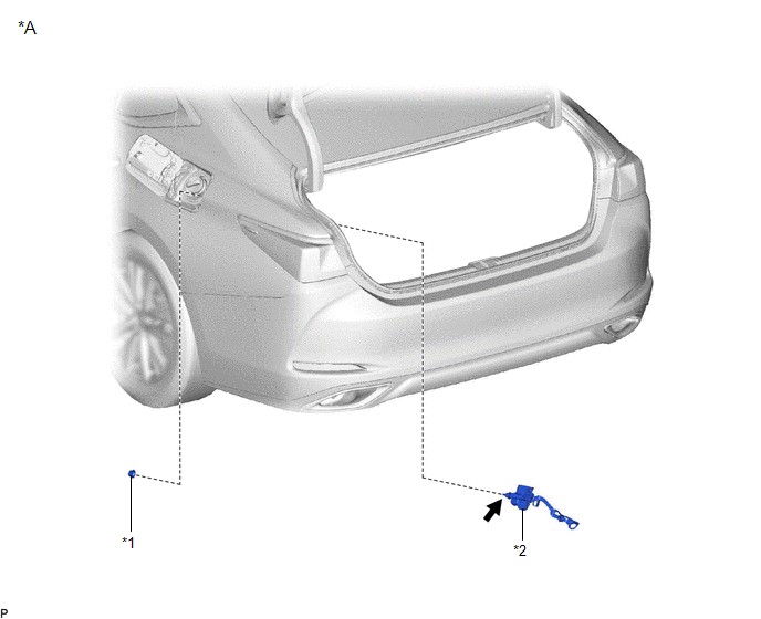
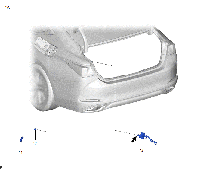
| *A | for Gasoline Model | - | - |
| *1 | FUEL FILLER OPENING LID LOCK RETAINER | *2 | FUEL LID LOCK WITH MOTOR ASSEMBLY |
.png) | MP grease | - | - |
ILLUSTRATION
| *A | for HV Model | - | - |
| *1 | FUEL FILLER OPENING LID LOCK COVER | *2 | FUEL FILLER OPENING LID LOCK RETAINER |
| *3 | FUEL LID LOCK WITH MOTOR ASSEMBLY | - | - |
| | MP grease | - | - |
READ NEXT:
 Removal
REMOVAL PROCEDURE 1. REMOVE LUGGAGE COMPARTMENT FLOOR MAT Click here 2. REMOVE SPARE WHEEL COVER TRAY Click here 3. REMOVE REAR FLOOR FINISH PLATE Click here 4. REMOVE LUGGAGE COMPARTMENT TRIM C
Inspection
INSPECTION PROCEDURE 1. INSPECT FUEL LID LOCK WITH MOTOR ASSEMBLY (a) Check the operation of the fuel lid lock with motor assembly (motor operation). (1) Apply auxiliary battery voltage to the fuel li
Installation
INSTALLATION PROCEDURE 1. INSTALL FUEL LID LOCK WITH MOTOR ASSEMBLY (a) Apply MP grease to the sliding parts of the fuel lid lock with motor assembly. (b) Connect the connector. (c) Engage the 2 claws
SEE MORE:
Installation
INSTALLATION PROCEDURE 1. INSTALL RADIO SETTING CONDENSER (a) Engage the claw to install a new terminal cover to the wire harness. NOTICE:
Make sure to hold the crimped side of the terminal when installing the wire harness to the terminal cover.
Make sure not to bend the exposed wire when
Right Headlight ECU Malfunction (B242C,B242D)
DESCRIPTION The headlight ECU sub-assembly LH or headlight ECU sub-assembly RH stores a DTC if it detects an internal malfunction. for LED Type Turn Signal Light DTC No. Detection Item DTC Detection Condition Trouble Area DTC Output from B242C Right Headlight ECU Malfunction
Th
© 2016-2026 Copyright www.lexguide.net
