Lexus ES: Installation
INSTALLATION
PROCEDURE
1. INSTALL FUEL LID LOCK WITH MOTOR ASSEMBLY
(a) Apply MP grease to the sliding parts of the fuel lid lock with motor assembly.
(b) Connect the connector.
(c) Engage the 2 claws.
(d) Engage the clamp to install the fuel lid lock with motor assembly.
2. INSTALL FUEL FILLER OPENING LID LOCK RETAINER (for Gasoline Model)
(a) Install the fuel filler opening lid lock retainer as shown in the illustration.
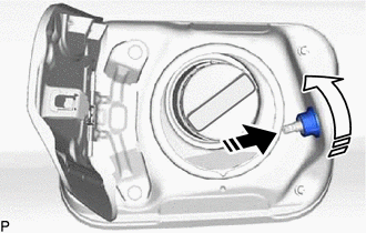
.png) | Install in this Direction (1) |
.png) | Turn in this Direction (2) |
3. INSTALL FUEL FILLER OPENING LID LOCK RETAINER (for HV Model)
(a) Install the fuel filler opening lid lock retainer as shown in the illustration.
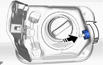
| | Install in this Direction (1) |
| | Turn in this Direction (2) |
4. INSTALL FUEL FILLER OPENING LID LOCK COVER (for HV Model)
(a) Engage the 2 claws to install the fuel filler opening lid lock cover as shown in the illustration.
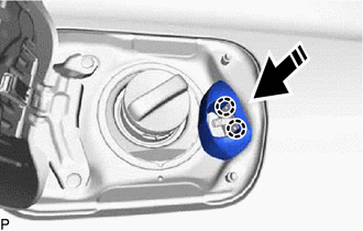
| | Install in this Direction |
5. INSTALL LUGGAGE COMPARTMENT TRIM INNER COVER LH
Click here .gif)
6. INSTALL LUGGAGE COMPARTMENT TRIM COVER LH
Click here
7. INSTALL REAR FLOOR FINISH PLATE
Click here
8. INSTALL SPARE WHEEL COVER TRAY
Click here
9. INSTALL LUGGAGE COMPARTMENT FLOOR MAT
Click here
READ NEXT:
 Components
COMPONENTS ILLUSTRATION *1 COWL SIDE TRIM BOARD LH *2 FRONT DOOR OPENING TRIM COVER LH *3 FRONT DOOR SCUFF PLATE LH *4 FUEL LID OPENER SWITCH (TRUNK AND FUEL SWITCH ASSEMBLY) *
Removal
REMOVAL PROCEDURE 1. REMOVE FRONT DOOR SCUFF PLATE LH Click here 2. REMOVE COWL SIDE TRIM BOARD LH Click here 3. REMOVE FRONT DOOR OPENING TRIM COVER LH Click here 4. REMOVE INSTRUMENT SIDE P
SEE MORE:
Parts Location
PARTS LOCATION ILLUSTRATION *A for Type A *B for Type B *1 HIGH PITCHED HORN ASSEMBLY *2 LOW PITCHED HORN ASSEMBLY *3 HORN RELAY *4 ENGINE ROOM RELAY BLOCK AND JUNCTION BLOCK ASSEMBLY - HORN FUSE ILLUSTRATION *A for LHD - - *1 SPIRAL CABLE SUB-ASSEMBL
Inspection
INSPECTION PROCEDURE 1. INSPECT HYBRID BATTERY TERMINAL BLOCK (a) Measure the resistance according to the value(s) in the table below. Standard Resistance: Tester Connection Condition Specified Condition Hybrid Battery Terminal Block Always Below 1 Ω If the result is not as sp
