Lexus ES: Removal
REMOVAL
PROCEDURE
1. REMOVE LUGGAGE COMPARTMENT FLOOR MAT
Click here .gif)
2. REMOVE SPARE WHEEL COVER TRAY
Click here
3. REMOVE REAR FLOOR FINISH PLATE
Click here
4. REMOVE LUGGAGE COMPARTMENT TRIM COVER LH
Click here
5. REMOVE LUGGAGE COMPARTMENT TRIM INNER COVER LH
Click here
6. REMOVE FUEL FILLER OPENING LID LOCK RETAINER (for Gasoline Model)
(a) Turn and remove the fuel filler opening lid lock retainer as indicated by the arrows, in the order shown in the illustration.
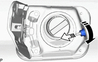
.png) | Turn in this Direction (1) |
.png) | Remove in this Direction (2) |
7. REMOVE FUEL FILLER OPENING LID LOCK COVER (for HV Model)
(a) Disengage the 2 claws and remove the fuel filler opening lid lock cover as shown in the illustration.
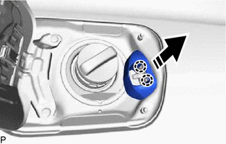
| | Remove in this Direction |
8. REMOVE FUEL FILLER OPENING LID LOCK RETAINER (for HV Model)
(a) Turn and remove the fuel filler opening lid lock retainer as indicated by the arrows, in the order shown in the illustration.
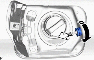
| | Turn in this Direction (1) |
| | Remove in this Direction (2) |
9. REMOVE FUEL LID LOCK WITH MOTOR ASSEMBLY
| (a) Disengage the clamp. |
|
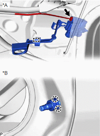
(b) Disengage the 2 claws.
(c) Disconnect the connector to remove the fuel lid lock with motor assembly.
READ NEXT:
 Inspection
INSPECTION PROCEDURE 1. INSPECT FUEL LID LOCK WITH MOTOR ASSEMBLY (a) Check the operation of the fuel lid lock with motor assembly (motor operation). (1) Apply auxiliary battery voltage to the fuel li
Installation
INSTALLATION PROCEDURE 1. INSTALL FUEL LID LOCK WITH MOTOR ASSEMBLY (a) Apply MP grease to the sliding parts of the fuel lid lock with motor assembly. (b) Connect the connector. (c) Engage the 2 claws
SEE MORE:
Roof Drip Side Finish Moulding
ComponentsCOMPONENTS ILLUSTRATION *1 CENTER ROOF DRIP SIDE FINISH MOULDING *2 NO. 1 ROOF DRIP SIDE FINISH MOULDING CLIP ● Non-reusable part - - RemovalREMOVAL CAUTION / NOTICE / HINT HINT:
Use the same procedure for the RH side and LH side.
The following procedure is
Removal
REMOVAL PROCEDURE 1. PRECAUTION (for HV Model) (a) w/o Navigation System: NOTICE:
When replacing the radio receiver assembly, always replace it with a new one. If a radio receiver assembly which was installed to another vehicle is used, the following may occur:
A communication malfunction DTC
