Lexus ES: Inspection
INSPECTION
PROCEDURE
1. INSPECT FUEL LID LOCK WITH MOTOR ASSEMBLY
(a) Check the operation of the fuel lid lock with motor assembly (motor operation).
(1) Apply auxiliary battery voltage to the fuel lid lock with motor assembly connector, and check the operation of the fuel lid lock with motor assembly.
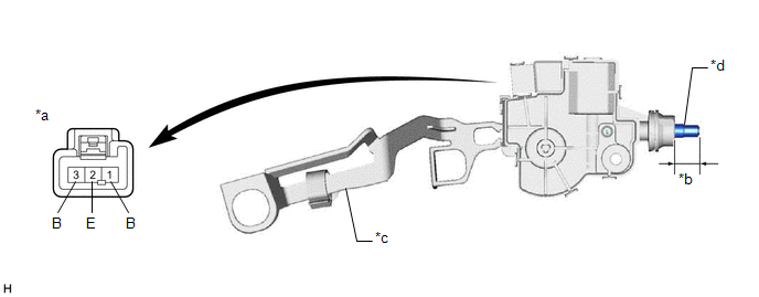
| *a | Component without harness connected (Fuel Lid Lock with Motor Assembly) | *b | Shaft Stroke |
| *c | Lever | *d | Shaft |
OK:
| Auxiliary Battery Connection | Specified Condition |
|---|---|
| Auxiliary battery positive (+) → Terminal 1 (B) Auxiliary battery negative (-) → Terminal 2 (E) | Shaft retracts |
If the result is not as specified, replace the fuel lid lock with motor assembly.
(b) Check the operation of the fuel lid lock with motor assembly (fuel lid courtesy switch).
(1) Measure the resistance according the value(s) in the table below.
Standard Resistance:
| Tester Connection | Condition | Specified Condition |
|---|---|---|
| 2 (E) - 3 (B) | Shaft not pushed (On) | Below 1 Ω |
| 2 (E) - 3 (B) | Shaft pushed (Off) | 10 kΩ or higher |
If the result is not as specified, replace the fuel lid lock with motor assembly.
(c) Measure the shaft stroke.
Standard:
| Area | Condition | Specified Condition |
|---|---|---|
| Shaft stroke | Lever pulled | 16.05 mm (0.632 in.) |
If the result is not as specified, replace the fuel lid lock with motor assembly.
READ NEXT:
 Installation
INSTALLATION PROCEDURE 1. INSTALL FUEL LID LOCK WITH MOTOR ASSEMBLY (a) Apply MP grease to the sliding parts of the fuel lid lock with motor assembly. (b) Connect the connector. (c) Engage the 2 claws
Components
COMPONENTS ILLUSTRATION *1 COWL SIDE TRIM BOARD LH *2 FRONT DOOR OPENING TRIM COVER LH *3 FRONT DOOR SCUFF PLATE LH *4 FUEL LID OPENER SWITCH (TRUNK AND FUEL SWITCH ASSEMBLY) *
SEE MORE:
Components
COMPONENTS ILLUSTRATION *1 FUEL PRESSURE SENSOR *2 NO. 1 FUEL PRESSURE SENSOR HOLDER Tightening torque for "Major areas involving basic vehicle performance such as moving/turning/stopping": N*m (kgf*cm, ft.*lbf) ● Non-reusable part
Components
COMPONENTS ILLUSTRATION *1 FRONT CENTER UPPER SUSPENSION BRACE SUB-ASSEMBLY - - Tightening torque for "Major areas involving basic vehicle performance such as moving/turning/stopping": N*m (kgf*cm, ft.*lbf) N*m (kgf*cm, ft.*lbf): Specified torque *T1 Bolt color black: 8.0
