Lexus ES: Components
COMPONENTS
ILLUSTRATION
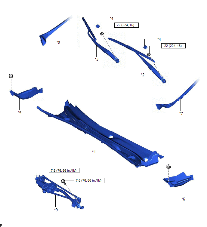
| *1 | COWL TOP VENTILATOR LOUVER SUB-ASSEMBLY | *2 | FRONT WIPER ARM AND BLADE ASSEMBLY LH |
| *3 | FRONT WIPER ARM AND BLADE ASSEMBLY RH | *4 | FRONT WIPER ARM HEAD CAP |
| *5 | NO. 2 COWL TOP PANEL INSULATOR | *6 | NO. 3 COWL TOP PANEL INSULATOR |
| *7 | WINDSHIELD OUTSIDE MOULDING LH | *8 | WINDSHIELD OUTSIDE MOULDING RH |
| *9 | WINDSHIELD WIPER MOTOR AND LINK ASSEMBLY | - | - |
.png) | N*m (kgf*cm, ft.*lbf): Specified torque | - | - |
ILLUSTRATION
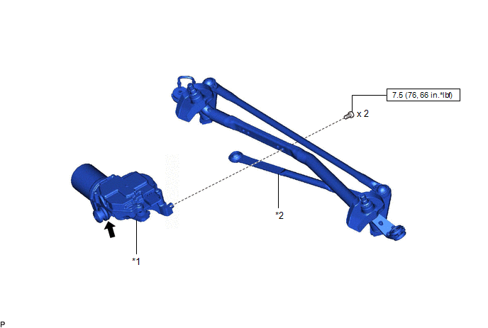
| *1 | WINDSHIELD WIPER MOTOR ASSEMBLY | *2 | WIPER LINK ASSEMBLY |
| | N*m (kgf*cm, ft.*lbf): Specified torque | .png) | MP grease |
READ NEXT:
 On-vehicle Inspection
ON-VEHICLE INSPECTION PROCEDURE 1. INSPECT WINDSHIELD WIPER MOTOR ASSEMBLY (a) for RH Side (1) Operate the windshield wiper motor assembly. (2) Stop the windshield wiper motor assembly operation. (
Removal
REMOVAL CAUTION / NOTICE / HINT NOTICE: Make sure to hold the front wiper arm while lifting it, as lifting the front wiper arm by the front wiper blade may damage or deform the front wiper blade. PROC
Inspection
INSPECTION CAUTION / NOTICE / HINT CAUTION: Be careful so that fingers and clothing do not get caught in the moving parts when performing this test. PROCEDURE 1. INSPECT WINDSHIELD WIPER MOTOR ASSEMBL
SEE MORE:
Fail-safe Chart
FAIL-SAFE CHART PROTECTION FUNCTION (a) The windshield wiper motor assembly operates the following protection functions if it detects an abnormal condition, in order to protect the wiper and washer system. Item Protection Content Conditions to Return to Normal Condition Overheat protectio
Removal
REMOVAL CAUTION / NOTICE / HINT The necessary procedures (adjustment, calibration, initialization, or registration) that must be performed after parts are removed and installed, or replaced during front door window frame moulding removal/installation are shown below. Necessary Procedure After Parts
© 2016-2026 Copyright www.lexguide.net
