Lexus ES: On-vehicle Inspection
ON-VEHICLE INSPECTION
PROCEDURE
1. INSPECT WINDSHIELD WIPER MOTOR ASSEMBLY
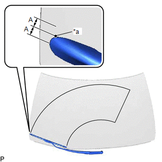
| (a) for RH Side (1) Operate the windshield wiper motor assembly. (2) Stop the windshield wiper motor assembly operation. (3) Check the automatic stop (park) position. HINT: After the front wiper motor is stopped, check the automatic stop position after lifting the wiper blade 2 times. Standard Clearance:
OK: The front wiper stops at the position shown in the illustration. |
|
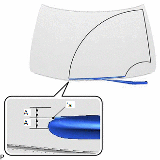
| (b) for LH Side (1) Operate the windshield wiper motor assembly. (2) Stop the windshield wiper motor assembly operation. (3) Check the automatic stop (park) position. HINT: After the front wiper motor is stopped, check the automatic stop position after lifting the wiper blade 2 times. Standard Clearance:
OK: The front wiper stops at the position shown in the illustration. |
|
READ NEXT:
 Removal
REMOVAL CAUTION / NOTICE / HINT NOTICE: Make sure to hold the front wiper arm while lifting it, as lifting the front wiper arm by the front wiper blade may damage or deform the front wiper blade. PROC
Inspection
INSPECTION CAUTION / NOTICE / HINT CAUTION: Be careful so that fingers and clothing do not get caught in the moving parts when performing this test. PROCEDURE 1. INSPECT WINDSHIELD WIPER MOTOR ASSEMBL
Installation
INSTALLATION CAUTION / NOTICE / HINT NOTICE: Make sure to hold the front wiper arm while lifting it, as lifting the front wiper arm by the front wiper blade may damage or deform the front wiper blade.
SEE MORE:
Luggage Compartment Door Closer Switch
ComponentsCOMPONENTS ILLUSTRATION *1 DOOR CONTROL SWITCH *2 LUGGAGE COMPARTMENT DOOR COVER *3 LUGGAGE LOCK CONTROL CABLE PLATE *4 SWITCH BEZEL RemovalREMOVAL PROCEDURE 1. REMOVE LUGGAGE LOCK CONTROL CABLE PLATE Click here 2. REMOVE SWITCH BEZEL Click here 3. REMOVE LUGGA
Components
COMPONENTS ILLUSTRATION *1 NO. 2 PARKING BRAKE WIRE ASSEMBLY *2 REAR AXLE HUB AND BEARING ASSEMBLY *3 REAR AXLE SHAFT NUT *4 REAR DISC *5 REAR DISC BRAKE CALIPER ASSEMBLY *6 REAR SKID CONTROL SENSOR *7 REAR DISC BRAKE DUST COVER SUB-ASSEMBLY *8 REAR DRIVE SHAF
