Lexus ES: Components
COMPONENTS
ILLUSTRATION
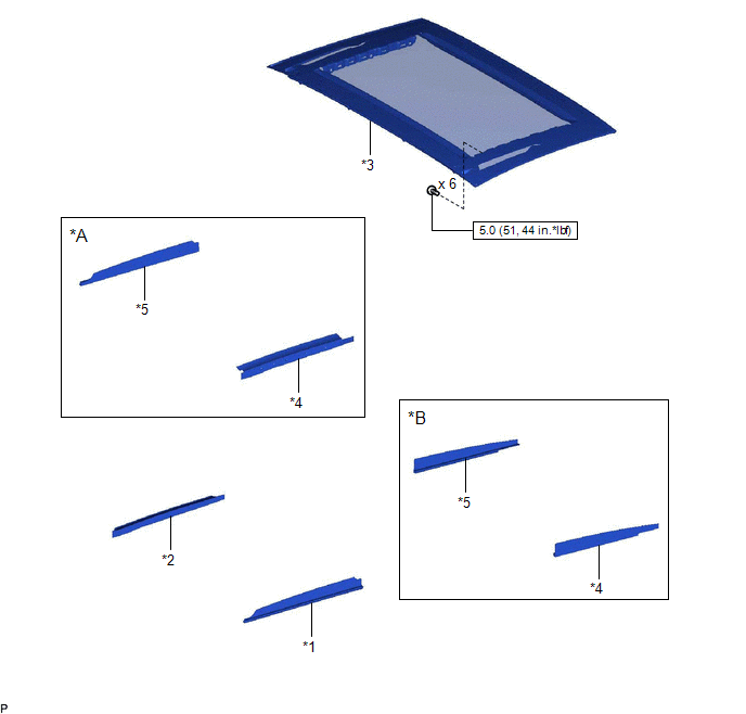
| *A | for Front Side | *B | for Rear Side |
| *1 | FRONT SLIDING ROOF GARNISH LH | *2 | FRONT SLIDING ROOF GARNISH RH |
| *3 | SLIDING ROOF GLASS SUB-ASSEMBLY | *4 | SLIDING ROOF SIDE GARNISH LH |
| *5 | SLIDING ROOF SIDE GARNISH RH | - | - |
.png) | N*m (kgf*cm, ft.*lbf): Specified torque | - | - |
ILLUSTRATION
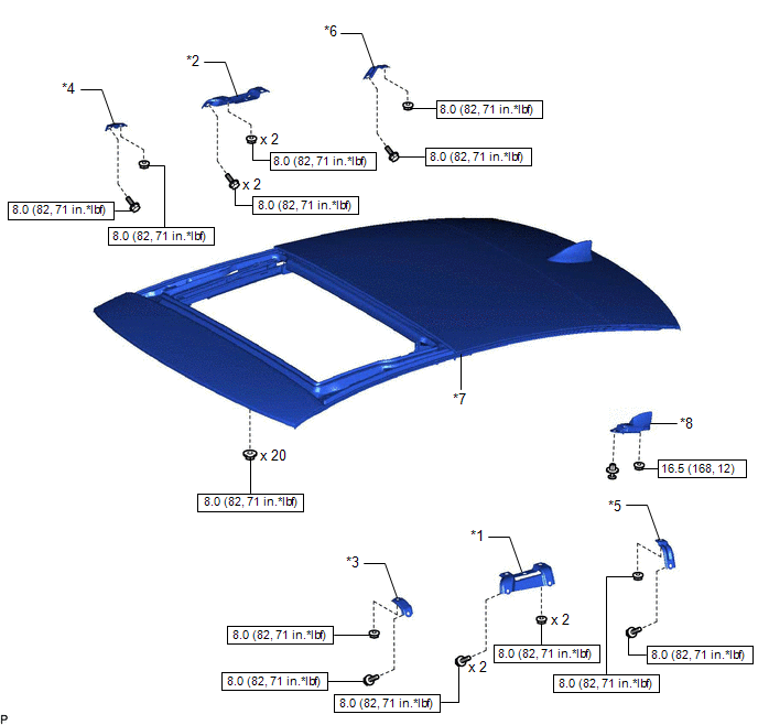
| *1 | CENTER SLIDING ROOF HOUSING MOUNTING BRACKET LH | *2 | CENTER SLIDING ROOF HOUSING MOUNTING BRACKET RH |
| *3 | FRONT SLIDING ROOF HOUSING MOUNTING BRACKET LH | *4 | FRONT SLIDING ROOF HOUSING MOUNTING BRACKET RH |
| *5 | REAR SLIDING ROOF HOUSING MOUNTING BRACKET LH | *6 | REAR SLIDING ROOF HOUSING MOUNTING BRACKET RH |
| *7 | SLIDING ROOF OR REMOVABLE ROOF HOUSING SUB-ASSEMBLY | *8 | TELEPHONE ANTENNA ASSEMBLY |
| | N*m (kgf*cm, ft.*lbf): Specified torque | - | - |
ILLUSTRATION
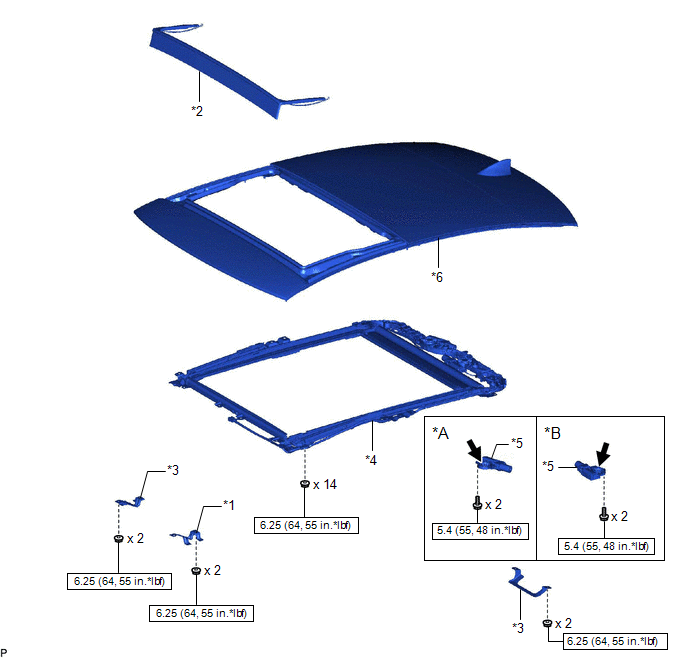
| *A | for Sliding Roof Glass | *B | for Roof Sunshade |
| *1 | NO. 2 ROOM LIGHT BRACKET | *2 | ROOF WIND DEFLECTOR PANEL SUB-ASSEMBLY |
| *3 | ROOM LIGHT BRACKET | *4 | SLIDE ROOF RAIL SUB-ASSEMBLY |
| *5 | SLIDING ROOF DRIVE GEAR ASSEMBLY | *6 | SLIDING ROOF HOUSING PANEL |
| | N*m (kgf*cm, ft.*lbf): Specified torque | .png) | MP grease |
ILLUSTRATION
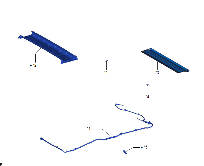
| *1 | NO. 2 ROOF WIRE | *2 | REAR SLIDING ROOF GARNISH |
| *3 | SUNSHADE TRIM SUB-ASSEMBLY | *4 | SLIDING ROOF SUNSHADE PLATE |
| *5 | Tape | - | - |
| ● | Non-reusable part | - | - |
READ NEXT:
 Removal
REMOVAL CAUTION / NOTICE / HINT The necessary procedures (adjustment, calibration, initialization or registration) that must be performed after parts are removed and installed, or replaced during slid
Disassembly
DISASSEMBLY PROCEDURE 1. REMOVE ROOF WIND DEFLECTOR PANEL SUB-ASSEMBLY (a) Disengage the 3 claws and 2 pins. (b) Move the roof wind deflector panel sub-assembly in the direction indicated by the arro
Reassembly
REASSEMBLY PROCEDURE 1. INSTALL SUNSHADE TRIM SUB-ASSEMBLY (a) Make sure that the No. 1 sliding roof shoe sub-assembly is positioned as shown in the illustration. HINT: Use the same procedure for t
SEE MORE:
Inverter "A" Cooling System Performance (P0A9300)
DTC SUMMARY MALFUNCTION DESCRIPTION This DTC indicates when the temperature sensor value inside the inverter has become abnormal. The cause of this malfunction may be one of the following: Internal inverter malfunction
Inverter internal circuit malfunction
Malfunction in ECU that controls the i
Precaution
PRECAUTION PRECAUTIONS FOR INSPECTING POWER SOURCE FOR MAIN BODY ECU (MULTIPLEX NETWORK BODY ECU) NOTICE: When disconnecting the cable from the negative (-) battery terminal, initialize the following systems after the cable is reconnected. System Name See Procedure Lane Control System (for
