Lexus ES: Removal
REMOVAL
CAUTION / NOTICE / HINT
The necessary procedures (adjustment, calibration, initialization or registration) that must be performed after parts are removed and installed, or replaced during sliding roof housing removal/installation are shown below.
Necessary Procedure After Parts Removed/Installed/Replaced| Replaced Part or Performed Procedure | Necessary Procedure | Effect/Inoperative Function When Necessary Procedures are not Performed | Link |
|---|---|---|---|
|
*: When performing learning using the Techstream.
Click here | |||
| Disconnect cable from negative (-) battery terminal | Perform steering sensor zero point calibration | Lane Control System (for Gasoline Model) | |
| Pre-collision System (for Gasoline Model) | |||
| Parking Support Brake System (for Gasoline Model)* | |||
| Lighting System (for Gasoline Model) | |||
| Memorize steering angle neutral point | Parking Assist Monitor System (for Gasoline Model) | | |
| Panoramic View Monitor System (for Gasoline Model) | | ||
| Initialize power trunk lid system | Power Trunk Lid System (for Gasoline Model) | | |
| Removal/installation of the front passenger seat | Zero point calibration (Occupant Classification System) |
| |
| Steering sensor | Steering angle zero point learning (Initialize parking support brake system) |
| |
| Parking Assist Monitor System (for Gasoline Model) | | |
| Steering angle zero point learning (Initialize panoramic view monitor system) | Panoramic View Monitor System (for Gasoline Model) | | |
| Initialize panoramic moon roof system (for Sliding Roof) |
| |
| Initialize panoramic moon roof system (for Roof Sunshade) |
| |
CAUTION:
Some of these service operations affect the SRS airbag system. Read the precautionary notices concerning the SRS airbag system before servicing.
.png)
Click here .gif)
NOTICE:
- After the engine switch is turned off, the radio receiver assembly records various types of memory and settings. As a result, after turning the engine switch off, make sure to wait at least 85 seconds before disconnecting the cable from the negative (-) battery terminal. (for Audio and Visual System)
- After the engine switch is turned off, the radio receiver assembly records various types of memory and settings. As a result, after turning the engine switch off, make sure to wait at least 85 seconds before disconnecting the cable from the negative (-) battery terminal. (for Navigation System)
PROCEDURE
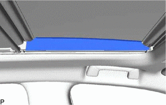
1. REMOVE FRONT SLIDING ROOF GARNISH LH
(a) Move the sunshade trim sub-assembly to the fully opened position.
| (b) Remove the front sliding roof garnish LH. |
|
2. REMOVE FRONT SLIDING ROOF GARNISH RH
HINT:
Use the same procedure as for the LH side.
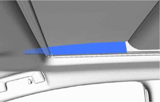
3. REMOVE SLIDING ROOF SIDE GARNISH LH (for Rear Side)
| (a) Remove the sliding roof side garnish LH. |
|
4. REMOVE SLIDING ROOF SIDE GARNISH RH (for Rear Side)
HINT:
Use the same procedure as for the LH side.
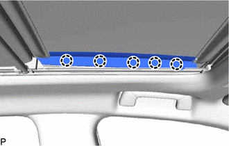
5. REMOVE SLIDING ROOF SIDE GARNISH LH (for Front Side)
(a) Move the sliding roof glass sub-assembly to the fully tilted up position.
| (b) Disengage the 5 claws to remove the sliding roof side garnish LH. |
|
6. REMOVE SLIDING ROOF SIDE GARNISH RH (for Front Side)
HINT:
Use the same procedure as for the LH side.
7. REMOVE SLIDING ROOF GLASS SUB-ASSEMBLY
(a) Move the sliding roof glass sub-assembly to the fully closed position.
(b) Using a T25 "TORX" socket wrench, remove the 6 screws and sliding roof glass sub-assembly.
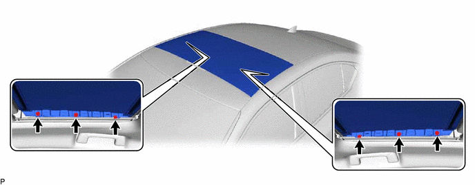
NOTICE:
To prevent the sliding roof glass sub-assembly and sliding roof drive gear assembly from becoming misaligned, move the sliding roof glass sub-assembly to the fully closed position before removing it.
8. REMOVE CURTAIN SHIELD AIRBAG ASSEMBLY LH
Click here
9. REMOVE CURTAIN SHIELD AIRBAG ASSEMBLY RH
HINT:
Use the same procedure as for the LH side.
10. REMOVE TELEPHONE ANTENNA ASSEMBLY
Click here
11. REMOVE FRONT SLIDING ROOF HOUSING MOUNTING BRACKET LH
(a) Remove the bolt, nut and front sliding roof housing mounting bracket LH.
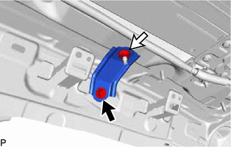
.png) | Bolt |
.png) | Nut |
12. REMOVE FRONT SLIDING ROOF HOUSING MOUNTING BRACKET RH
HINT:
Use the same procedure as for the LH side.
13. REMOVE CENTER SLIDING ROOF HOUSING MOUNTING BRACKET LH
(a) Remove the 2 bolts, 2 nuts and center sliding roof housing mounting bracket LH.
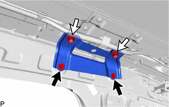
| | Bolt |
| | Nut |
14. REMOVE CENTER SLIDING ROOF HOUSING MOUNTING BRACKET RH
HINT:
Use the same procedure as for the LH side.
15. REMOVE REAR SLIDING ROOF HOUSING MOUNTING BRACKET LH
(a) Remove the bolt, nut and rear sliding roof housing mounting bracket LH.
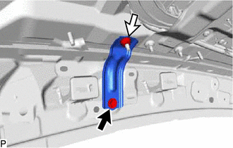
| | Bolt |
| | Nut |
16. REMOVE REAR SLIDING ROOF HOUSING MOUNTING BRACKET RH
HINT:
Use the same procedure as for the LH side.
17. REMOVE SLIDING ROOF OR REMOVABLE ROOF HOUSING SUB-ASSEMBLY
(a) Remove the 20 nuts.
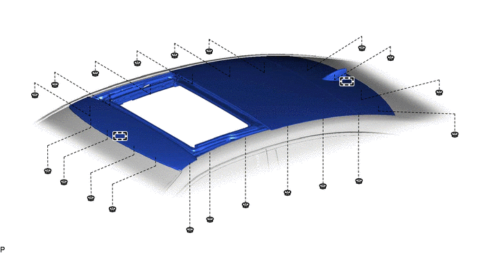
(b) Disengage the 2 guides and remove the sliding roof or removable roof housing sub-assembly.
READ NEXT:
 Disassembly
DISASSEMBLY PROCEDURE 1. REMOVE ROOF WIND DEFLECTOR PANEL SUB-ASSEMBLY (a) Disengage the 3 claws and 2 pins. (b) Move the roof wind deflector panel sub-assembly in the direction indicated by the arro
Reassembly
REASSEMBLY PROCEDURE 1. INSTALL SUNSHADE TRIM SUB-ASSEMBLY (a) Make sure that the No. 1 sliding roof shoe sub-assembly is positioned as shown in the illustration. HINT: Use the same procedure for t
Installation
INSTALLATION PROCEDURE 1. INSTALL SLIDING ROOF OR REMOVABLE ROOF HOUSING SUB-ASSEMBLY (a) Pass a string under the windshield outside moulding as shown in the illustration. *1 Windshield Outside
SEE MORE:
Hybrid/EV Powertrain Control Module EEPROM Calibration / Parameter Memory Failure (P062F46)
DESCRIPTION The hybrid vehicle control ECU monitors its internal operation and will store these DTCs when it detects an internal malfunction. DTC No. Detection Item DTC Detection Condition Trouble Area MIL Warning Indicate P062F46 Hybrid/EV Powertrain Control Module EEPROM Calibra
Removal
REMOVAL CAUTION / NOTICE / HINT The necessary procedures (adjustment, calibration, initialization or registration) that must be performed after parts are removed and installed, or replaced during fuel pump with filter assembly removal/installation are shown below. Necessary Procedures After Parts Re
