
Lexus ES: Components
COMPONENTS
ILLUSTRATION
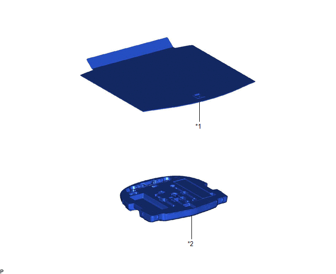
| *1 | LUGGAGE COMPARTMENT FLOOR MAT | *2 | SPARE WHEEL COVER TRAY |
ILLUSTRATION
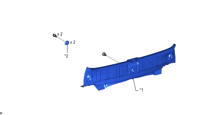
| *1 | REAR FLOOR FINISH PLATE | *2 | LUGGAGE HOLD BELT STRIKER ASSEMBLY |
ILLUSTRATION
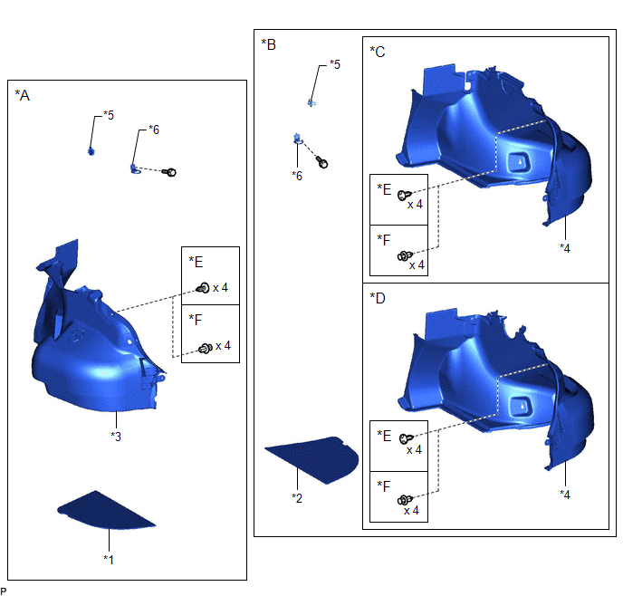
| *A | for LH Side | *B | for RH Side |
| *C | w/o Power Trunk Lid System | *D | w/ Power Trunk Lid System |
| *E | for Type A | *F | for Type B |
| *1 | LUGGAGE COMPARTMENT TRIM COVER LH | *2 | LUGGAGE COMPARTMENT TRIM COVER RH |
| *3 | LUGGAGE COMPARTMENT TRIM INNER COVER LH | *4 | LUGGAGE COMPARTMENT TRIM INNER COVER RH |
| *5 | ROPE HOOK | *6 | LUGGAGE HOLD BELT STRIKER ASSEMBLY |
ILLUSTRATION
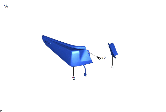
| *A | for TMC Made | - | - |
| *1 | REAR COMBINATION LIGHT COVER | *2 | REAR COMBINATION LIGHT LENS AND BODY |
ILLUSTRATION
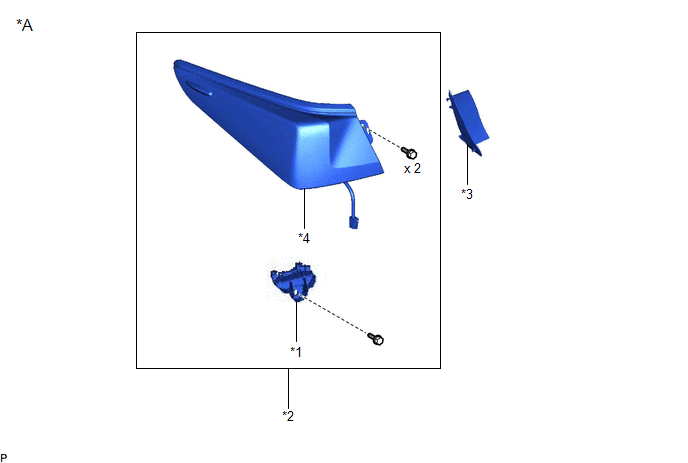
| *A | for TMMK Made | - | - |
| *1 | REAR BUMPER UPPER RETAINER | *2 | REAR COMBINATION LIGHT ASSEMBLY |
| *3 | REAR COMBINATION LIGHT COVER | *4 | REAR COMBINATION LIGHT LENS AND BODY |
READ NEXT:
 Removal
REMOVAL CAUTION / NOTICE / HINT The necessary procedures (adjustment, calibration, initialization, or registration) that must be performed after parts are removed and installed, or replaced during rea
Inspection
INSPECTION PROCEDURE 1. INSPECT REAR COMBINATION LIGHT LENS AND BODY LH (for TMC Made) *a Component without harness connected (Rear Combination Light Lens and Body LH) (a) Apply auxiliary bat
Installation
INSTALLATION CAUTION / NOTICE / HINT HINT:
Use the same procedure for the RH side and LH side.
The following procedure is for the LH side.
PROCEDURE 1. INSTALL REAR COMBINATION LIGHT ASSEMBLY
SEE MORE:
Data List / Active Test
DATA LIST / ACTIVE TEST DATA LIST HINT: Using the Techstream to read the Data List allows the values or states of switches, sensors, actuators and other items to be read without removing any parts. This non-intrusive inspection can be very useful because intermittent conditions or signals may be dis
Terminals Of Ecu
TERMINALS OF ECU CHECK OUTER MIRROR CONTROL ECU ASSEMBLY (DRIVER DOOR) (a) Disconnect the J28 outer mirror control ECU assembly (driver door) connector. (b) Measure the voltage and resistance according to the value(s) in the table below. HINT: Measure the values on the wire harness side with the co
© 2016-2026 Copyright www.lexguide.net
