Lexus ES: Components
Lexus ES (XZ10) Service Manual / Vehicle Exterior / Lighting (ext) / Hazard Warning Switch / Components
COMPONENTS
ILLUSTRATION
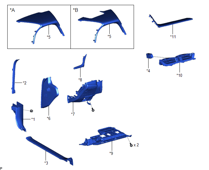
| *A | w/o Headup Display | *B | w/ Headup Display |
| *1 | COWL SIDE TRIM BOARD LH | *2 | FRONT DOOR OPENING TRIM COVER LH |
| *3 | FRONT DOOR SCUFF PLATE LH | *4 | HAZARD WARNING SIGNAL SWITCH ASSEMBLY |
| *5 | INSTRUMENT CLUSTER FINISH PANEL SUB-ASSEMBLY | *6 | INSTRUMENT SIDE PANEL LH |
| *7 | LOWER INSTRUMENT PANEL FINISH PANEL SUB-ASSEMBLY | *8 | NO. 1 INSTRUMENT CLUSTER MOULDING |
| *9 | NO. 1 INSTRUMENT PANEL UNDER COVER SUB-ASSEMBLY | *10 | NO. 2 INSTRUMENT PANEL REGISTER ASSEMBLY |
| *11 | UPPER INSTRUMENT PANEL FINISH PANEL SUB-ASSEMBLY | - | - |
READ NEXT:
 Removal
REMOVAL PROCEDURE 1. REMOVE AIR CONDITIONING CONTROL ASSEMBLY Click here 2. REMOVE FRONT DOOR SCUFF PLATE LH Click here 3. REMOVE COWL SIDE TRIM BOARD LH Click here 4. REMOVE FRONT DOOR OPENING
Inspection
INSPECTION PROCEDURE 1. INSPECT HAZARD WARNING SIGNAL SWITCH ASSEMBLY *a Component without harness connected (Hazard Warning Signal Switch Assembly) (a) Measure the resistance according to th
Installation
INSTALLATION PROCEDURE 1. INSTALL HAZARD WARNING SIGNAL SWITCH ASSEMBLY (a) Engage the 2 claws to install the hazard warning signal switch assembly. Install in this Direction 2. INSTALL NO.
SEE MORE:
Relay
On-vehicle InspectionON-VEHICLE INSPECTION PROCEDURE 1. INSPECT IGCT RELAY (IGCT) (a) Measure the resistance according to the value(s) in the table below. Standard Resistance: Tester Connection Condition Specified Condition 3 - 5 Auxiliary battery voltage not applied between termin
Problem Symptoms Table
PROBLEM SYMPTOMS TABLE NOTICE:
Depending on the parts that are replaced during vehicle inspection or maintenance, performing initialization, registration or calibration may be needed. Refer to Precaution for Navigation System.
Click here
When replacing the radio receiver assembly or navigatio
© 2016-2026 Copyright www.lexguide.net
