Lexus ES: Components
Lexus ES (XZ10) Service Manual / Suspension / Rear Suspension / Rear Stabilizer Bar (for Awd) / Components
COMPONENTS
ILLUSTRATION
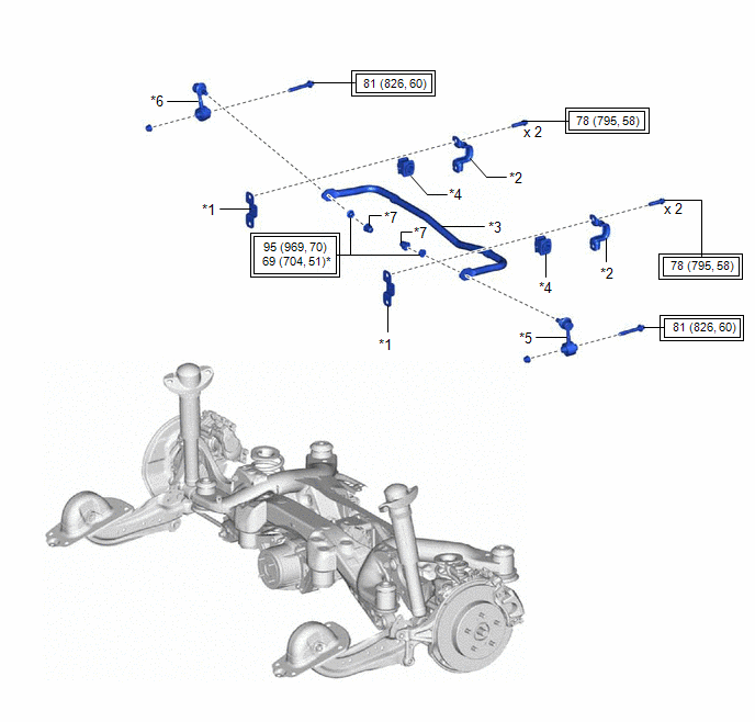
| *1 | REAR LOWER STABILIZER BRACKET | *2 | REAR NO. 1 STABILIZER BAR BRACKET |
| *3 | REAR STABILIZER BAR | *4 | REAR STABILIZER BUSHING |
| *5 | REAR STABILIZER LINK ASSEMBLY LH | *6 | REAR STABILIZER LINK ASSEMBLY RH |
| *7 | CAP | - | - |
.png) | Tightening torque for "Major areas involving basic vehicle performance such as moving/turning/stopping": N*m (kgf*cm, ft.*lbf) | * | For use with a ball joint lock nut wrench |
READ NEXT:
 Removal
REMOVAL CAUTION / NOTICE / HINT The necessary procedures (adjustment, calibration, initialization, or registration) that must be performed after parts are removed and installed, or replaced during rea
Inspection
INSPECTION PROCEDURE 1. INSPECT REAR STABILIZER LINK ASSEMBLY (a) Inspect the turning torque of the ball joint. (1) Secure the rear stabilizer link assembly in a vise using aluminum plates. NOTICE: D
Installation
INSTALLATION PROCEDURE 1. INSTALL REAR STABILIZER BUSHING (a) Install the 2 rear stabilizer bushings to the outside of the stoppers on the rear stabilizer bar. NOTICE: Be sure to install the rear s
SEE MORE:
Definition Of Terms
DEFINITION OF TERMS Term Definition Monitor Description Description of what the skid control ECU (brake booster with master cylinder assembly) monitors and how it detects malfunctions (monitoring purpose and details). Related DTCs Group of diagnostic trouble codes that are output by
Generator Shutdown Stuck Off (P1C6C9F)
DTC SUMMARY MALFUNCTION DESCRIPTION The hybrid vehicle control ECU detects malfunctions which prevent the generator (MG1) inverter shutdown circuit from shutting down the hybrid vehicle control system. Detection is performed during the shutdown sequence when the power switch is turned off. If genera
© 2016-2026 Copyright www.lexguide.net
