
Lexus ES: Components
COMPONENTS
ILLUSTRATION
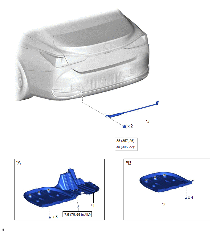
| *A | for A25A-FXS | *B | for 2GR-FKS |
| *1 | REAR FLOOR SIDE MEMBER COVER | *2 | REAR NO. 1 FLOOR BOARD |
| *3 | SUSPENSION TOWER DAMPER | - | - |
 | N*m (kgf*cm, ft.*lbf): Specified torque | * | For use with a union nut wrench |
READ NEXT:
 Components
COMPONENTS ILLUSTRATION *A for A25A-FKS *B for A25A-FXS *C for 2GR-FKS - - *1 REAR FLOOR SIDE MEMBER COVER *2 REAR NO. 1 FLOOR BOARD *3 SUSPENSION TOWER DAMPER -
Removal
REMOVAL PROCEDURE 1. REMOVE REAR NO. 1 FLOOR BOARD (for 2GR-FKS) (a) Remove the 4 clips (A). (b) Disengage the 3 grommets (B) and 2 clips (C) to remove the rear No. 1 floor board. 2. RE
Removal
REMOVAL PROCEDURE 1. REMOVE REAR NO. 1 FLOOR BOARD (for 2GR-FKS) (a) Remove the 4 clips (A). (b) Disengage the 3 grommets (B) and 2 clips (C) to remove the rear No. 1 floor board. 2. RE
SEE MORE:
Precaution
PRECAUTION CHARGING SYSTEM PRECAUTION CAUTION:
Orange wire harnesses and connectors indicate high-voltage circuits. To prevent electric shock, always follow the procedure described in the repair manual. Click here
To prevent electric shock, wear insulated gloves when working on wire harnesse
Inspection
INSPECTION PROCEDURE 1. INSPECT CONNECTING ROD THRUST CLEARANCE (a) Install the connecting rod cap. Click here (b) Using a dial indicator, measure the thrust clearance while moving the connecting rod back and forth. Standard Thrust Clearance: 0.15 to 0.40 mm (0.00591 to 0.0157 in.) Maximum Thr
© 2016-2026 Copyright www.lexguide.net
