Lexus ES: Components
COMPONENTS
ILLUSTRATION
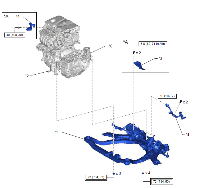
| *A | for A25A-FXS | - | - |
| *1 | FRONT FRAME ASSEMBLY | *2 | FUEL DELIVERY GUARD |
| *3 | STEERING GEAR HEAT INSULATOR | *4 | WIRE HARNESS |
| *5 | FRONT ENGINE MOUNTING INSULATOR | *6 | REAR ENGINE MOUNTING INSULATOR |
.png) | Tightening torque for "Major areas involving basic vehicle performance such as moving/turning/stopping": N*m (kgf*cm, ft.*lbf) | .png) | N*m (kgf*cm, ft.*lbf): Specified torque |
ILLUSTRATION
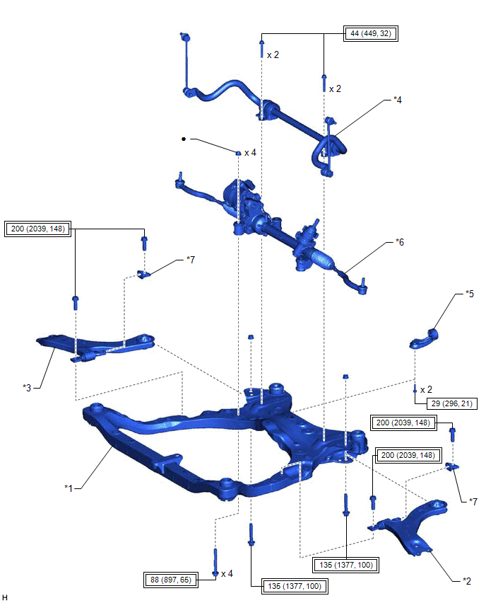
| *1 | FRONT FRAME ASSEMBLY | *2 | FRONT LOWER NO. 1 SUSPENSION ARM SUB-ASSEMBLY LH |
| *3 | FRONT LOWER NO. 1 SUSPENSION ARM SUB-ASSEMBLY RH | *4 | FRONT STABILIZER BAR WITH BRACKET |
| *5 | NO. 2 EXHAUST PIPE SUPPORT BRACKET | *6 | RACK AND PINION POWER STEERING GEAR ASSEMBLY |
| *7 | FRONT LOWER ARM BUSHING STOPPER | - | - |
| | Tightening torque for "Major areas involving basic vehicle performance such as moving/turning/stopping": N*m (kgf*cm, ft.*lbf) | | N*m (kgf*cm, ft.*lbf): Specified torque |
| ● | Non-reusable part | - | - |
ILLUSTRATION
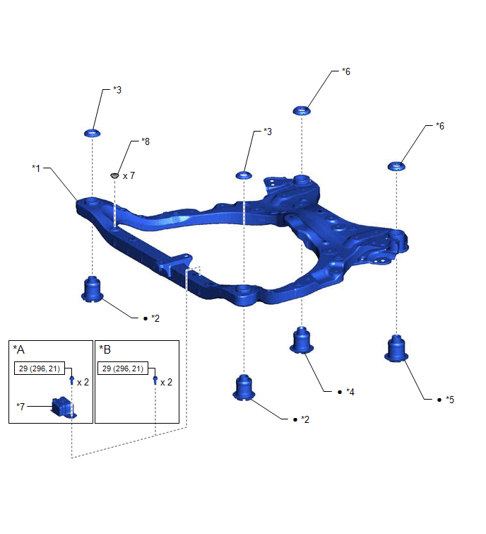
| *A | for 2GR-FKS | *B | for A25A-FXS |
| *1 | FRONT FRAME ASSEMBLY | *2 | FRONT SUSPENSION MEMBER BODY MOUNTING FRONT CUSHION |
| *3 | FRONT SUSPENSION MEMBER BODY MOUNTING FRONT STOPPER | *4 | FRONT SUSPENSION MEMBER BODY MOUNTING REAR CUSHION |
| *5 | FRONT SUSPENSION MEMBER BODY MOUNTING REAR CUSHION LH | *6 | FRONT SUSPENSION MEMBER BODY MOUNTING REAR STOPPER |
| *7 | FRONT SUSPENSION MEMBER DYNAMIC DAMPER | *8 | HOLE PLUG |
| | N*m (kgf*cm, ft.*lbf): Specified torque | ● | Non-reusable part |
READ NEXT:
 Components
COMPONENTS ILLUSTRATION *A for A25A-FKS, A25A-FXS *B for AWD *1 FRONT FRAME ASSEMBLY *2 FUEL DELIVERY GUARD *3 FUEL PUMP PROTECTOR *4 STEERING GEAR HEAT INSULATOR *5
Removal
REMOVAL CAUTION / NOTICE / HINT The necessary procedures (adjustment, calibration, initialization, or registration) that must be performed after parts are removed and installed, or replaced during fro
Installation
INSTALLATION PROCEDURE 1. INSTALL HOLE PLUG (a) Install the 7 hole plugs to the front frame assembly. HINT: There are 2 different shapes of hole plug. 2. INSTALL FRONT SUSPENSION MEMBER BODY MOUNTING
SEE MORE:
(Horizontality) G Sensor Malfunction (C1787)
DESCRIPTION The absorber control ECU receives a signal from the yaw rate and acceleration sensor (airbag ECU assembly) via CAN communication. DTC No. Detection Item DTC Detection Condition Trouble Area Warning Indicate Memory C1787 (Horizontality) G Sensor Malfunction While the
Removal
REMOVAL CAUTION / NOTICE / HINT The necessary procedures (adjustment, calibration, initialization or registration) that must be performed after parts are removed and installed, or replaced during engine assembly removal/installation are shown below. Necessary Procedure After Parts Removed/Installed/
