Lexus ES: Components
COMPONENTS
ILLUSTRATION
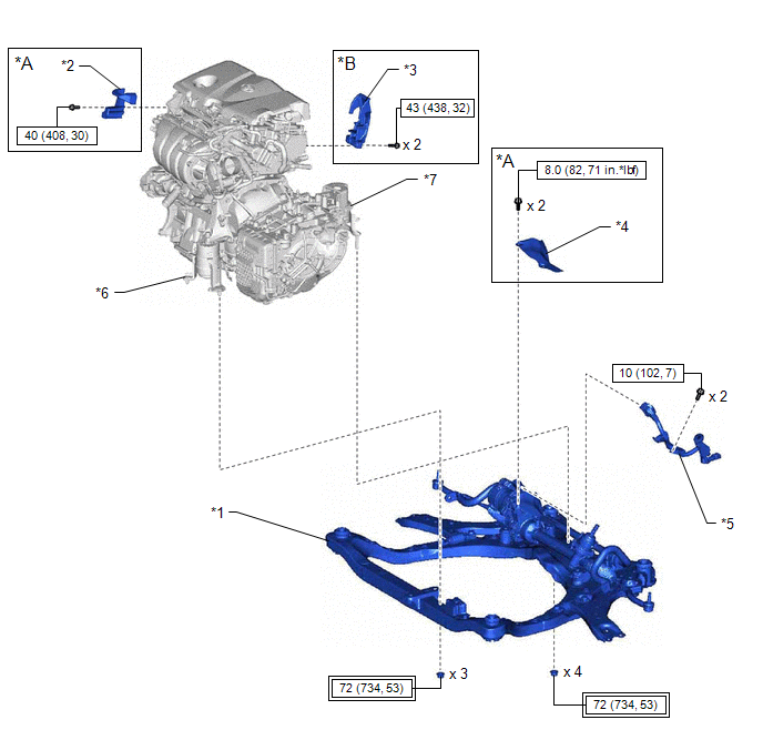
| *A | for A25A-FKS, A25A-FXS | *B | for AWD |
| *1 | FRONT FRAME ASSEMBLY | *2 | FUEL DELIVERY GUARD |
| *3 | FUEL PUMP PROTECTOR | *4 | STEERING GEAR HEAT INSULATOR |
| *5 | WIRE HARNESS | *6 | FRONT ENGINE MOUNTING INSULATOR |
| *7 | REAR ENGINE MOUNTING INSULATOR | - | - |
.png) | Tightening torque for "Major areas involving basic vehicle performance such as moving/turning/stopping": N*m (kgf*cm, ft.*lbf) | .png) | N*m (kgf*cm, ft.*lbf): Specified torque |
ILLUSTRATION
.png)
| *1 | FRONT FRAME ASSEMBLY | *2 | FRONT LOWER NO. 1 SUSPENSION ARM SUB-ASSEMBLY LH |
| *3 | FRONT LOWER NO. 1 SUSPENSION ARM SUB-ASSEMBLY RH | *4 | FRONT STABILIZER BAR WITH BRACKET |
| *5 | NO. 2 EXHAUST PIPE SUPPORT BRACKET | *6 | RACK AND PINION POWER STEERING GEAR ASSEMBLY |
| *7 | FRONT LOWER ARM BUSHING STOPPER | - | - |
| | Tightening torque for "Major areas involving basic vehicle performance such as moving/turning/stopping": N*m (kgf*cm, ft.*lbf) | | N*m (kgf*cm, ft.*lbf): Specified torque |
| ● | Non-reusable part | - | - |
ILLUSTRATION
.png)
| *A | for A25A-FKS, 2GR-FKS | *B | for A25A-FXS |
| *1 | FRONT FRAME ASSEMBLY | *2 | FRONT SUSPENSION MEMBER BODY MOUNTING FRONT CUSHION |
| *3 | FRONT SUSPENSION MEMBER BODY MOUNTING FRONT STOPPER | *4 | FRONT SUSPENSION MEMBER BODY MOUNTING REAR CUSHION |
| *5 | FRONT SUSPENSION MEMBER BODY MOUNTING REAR CUSHION LH | *6 | FRONT SUSPENSION MEMBER BODY MOUNTING REAR STOPPER |
| *7 | FRONT SUSPENSION MEMBER DYNAMIC DAMPER | *8 | HOLE PLUG |
| | N*m (kgf*cm, ft.*lbf): Specified torque | ● | Non-reusable part |
READ NEXT:
 Removal
REMOVAL CAUTION / NOTICE / HINT The necessary procedures (adjustment, calibration, initialization, or registration) that must be performed after parts are removed and installed, or replaced during fro
Installation
INSTALLATION PROCEDURE 1. INSTALL HOLE PLUG (a) Install the 7 hole plugs to the front frame assembly. HINT: There are 2 different shapes of hole plug. 2. INSTALL FRONT SUSPENSION MEMBER BODY MOUNTING
Installation
INSTALLATION PROCEDURE 1. INSTALL HOLE PLUG (a) Install the 7 hole plugs to the front frame assembly. HINT: There are 2 different shapes of hole plug. 2. INSTALL FRONT SUSPENSION MEMBER BODY MOUNTING
SEE MORE:
Inspection
INSPECTION PROCEDURE 1. INSPECT LUGGAGE DOOR OPENING CANCEL SWITCH ASSEMBLY (a) Check the resistance. (1) Measure the resistance according to the value(s) in the table below. Standard Resistance: Tester Connection Switch Condition Specified Condition 2 (B) - 1 (L) Switch on Below
Transmission (Shaft) Mechanical Linkage Failure (P314779)
DTC SUMMARY Refer to the DTC summary for DTC P1C7779. Click here DESCRIPTION Refer to the description for DTC P1C7779. Click here DTC No. Detection Item DTC Detection Condition Trouble Area MIL Warning Indicate P314779 Transmission (Shaft) Mechanical Linkage Failure Drive fo
