Lexus ES: Installation
INSTALLATION
PROCEDURE
1. INSTALL HOLE PLUG
(a) Install the 7 hole plugs to the front frame assembly.
HINT:
There are 2 different shapes of hole plug.
.png)
2. INSTALL FRONT SUSPENSION MEMBER BODY MOUNTING REAR CUSHION LH
(a) Align a new front suspension member body mounting rear cushion LH as shown in the illustration and set it to the front frame assembly.
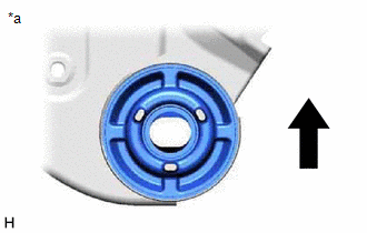
| *a | View from Underneath |
.png) | Front of the Vehicle |
NOTICE:
- Position the front suspension member body mounting rear cushion LH in the correct direction.
- Do not apply lubricant to the outer sleeve of the front suspension member body mounting rear cushion LH.
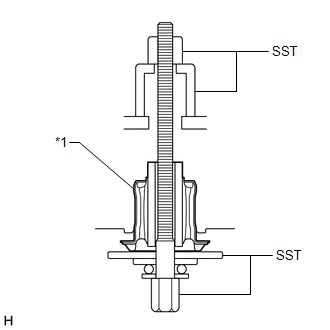
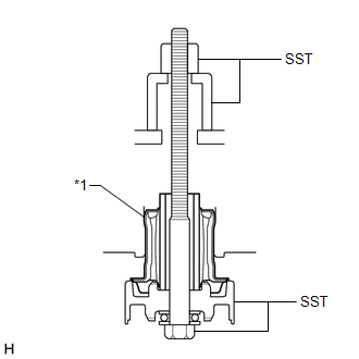
| (b) Install SST as shown in the illustration. SST: 09570-24011 SST: 09830-10010 09830-01010 09830-01020 09830-01040 09830-01060 NOTICE: Apply molybdenum grease to the threads and tip of the SST center bolt before use. |
|
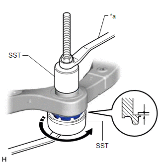
(c) Using SST, install the front suspension member body mounting rear cushion LH as shown in the illustration.
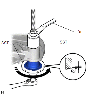
| *a | Hold |
.png) | Turn |
NOTICE:
Check that there is no clearance between the front frame assembly and the front suspension member body mounting rear cushion LH.
3. INSTALL FRONT SUSPENSION MEMBER BODY MOUNTING REAR CUSHION
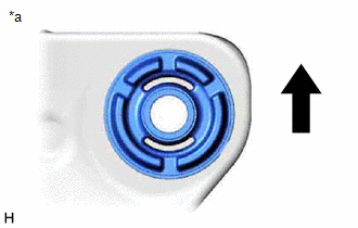
(a) Align a new front suspension member body mounting rear cushion as shown in the illustration and set it to the front frame assembly.

| *a | View from Underneath |
| | Front of the Vehicle |
NOTICE:
- Position the front suspension member body mounting rear cushion in the correct direction.
- Do not apply lubricant to the outer sleeve of the front suspension member body mounting rear cushion.
(b) Install SST using the same procedure as for the front suspension member body mounting rear cushion LH.
SST: 09570-24011
SST: 09830-10010
09830-01010
09830-01020
09830-01040
09830-01060
NOTICE:
Apply molybdenum grease to the threads and tip of the SST center bolt before use.
(c) Using SST, install the front suspension member body mounting rear cushion.
NOTICE:
Check that there is no clearance between the front frame assembly and the front suspension member body mounting rear cushion.
HINT:
Perform the same procedure as for the front suspension member body mounting rear cushion LH.
4. INSTALL FRONT SUSPENSION MEMBER BODY MOUNTING FRONT CUSHION (for LH Side)
(a) Align a new front suspension member body mounting front cushion as shown in the illustration and set it to the front frame assembly.
| *a | View from Underneath |
| | Front of the Vehicle |
NOTICE:
- Position the front suspension member body mounting front cushion in the correct direction.
- Do not apply lubricant to the outer sleeve of the front suspension member body mounting front cushion.
| (b) Install SST as shown in the illustration. SST: 09830-10010 09830-01010 09830-01020 09830-01030 09830-01060 NOTICE:
|
|
(c) Using SST, install the front suspension member body mounting front cushion as shown in the illustration.
| *a | Hold |
| | Turn |
NOTICE:
Check that there is no clearance between the front frame assembly and the front suspension member body mounting front cushion.
5. INSTALL FRONT SUSPENSION MEMBER BODY MOUNTING FRONT CUSHION (for RH Side)
(a) Align a new front suspension member body mounting front cushion as shown in the illustration and set it to the front frame assembly.

| *a | View from Underneath |
| | Front of the Vehicle |
NOTICE:
- Position the front suspension member body mounting front cushion in the correct direction.
- Do not apply lubricant to the outer sleeve of the front suspension member body mounting front cushion.
(b) Install SST using the same procedure as for the LH side.
SST: 09830-10010
09830-01010
09830-01020
09830-01030
09830-01060
NOTICE:
- Be sure to install SST (09830-01030) in the correct direction.
- Apply molybdenum grease to the threads and tip of the SST center bolt before use.
(c) Using SST, install the front suspension member body mounting front cushion.
NOTICE:
Check that there is no clearance between the front frame assembly and the front suspension member body mounting front cushion.
HINT:
Perform the same procedure as for the LH side.
6. INSTALL FRONT SUSPENSION MEMBER BODY MOUNTING REAR STOPPER
(a) Install the 2 front suspension member body mounting rear stoppers to the front frame assembly.
7. INSTALL FRONT SUSPENSION MEMBER BODY MOUNTING FRONT STOPPER
(a) Install the 2 front suspension member body mounting front stoppers to the front frame assembly.
8. INSTALL FRONT SUSPENSION MEMBER DYNAMIC DAMPER (for 2GR-FKS)
(a) Install the front suspension member dynamic damper to the front frame assembly with the 2 bolts.
Torque:
29 N·m {296 kgf·cm, 21 ft·lbf}
9. INSTALL BOLT (for A25A-FXS)
(a) Install the 2 bolts to the front frame assembly.
Torque:
29 N·m {296 kgf·cm, 21 ft·lbf}
10. INSTALL NO. 2 EXHAUST PIPE SUPPORT BRACKET
(a) Install the No. 2 exhaust pipe support bracket to the front frame assembly with the 2 bolts.
Torque:
29 N·m {296 kgf·cm, 21 ft·lbf}
11. INSTALL FRONT LOWER NO. 1 SUSPENSION ARM SUB-ASSEMBLY LH
(a) Install the front lower arm bushing stopper to the front lower No. 1 suspension arm sub-assembly LH.
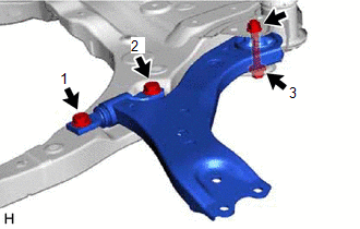
| (b) Install the front lower No. 1 suspension arm sub-assembly LH to the front frame assembly with the 3 bolts and nut in the order shown in the illustration. Torque: Bolt (1), (2) : 200 N·m {2039 kgf·cm, 148 ft·lbf} Bolt (3) : 135 N·m {1377 kgf·cm, 100 ft·lbf} NOTICE: Because the nut has its own stopper, do not turn the nut. Tighten the bolt with the nut secured. |
|
12. INSTALL FRONT LOWER NO. 1 SUSPENSION ARM SUB-ASSEMBLY RH
HINT:
Perform the same procedure as for the LH side.
13. INSTALL RACK AND PINION POWER STEERING GEAR ASSEMBLY
Click here .gif)
14. INSTALL FRONT STABILIZER BAR WITH BRACKET
Click here
15. INSTALL FRONT FRAME ASSEMBLY
(a) Install the rear engine mounting insulator to the front frame assembly with the 4 nuts.
Torque:
72 N·m {734 kgf·cm, 53 ft·lbf}
(b) Install the front engine mounting insulator to the front frame assembly with the 3 nuts.
Torque:
72 N·m {734 kgf·cm, 53 ft·lbf}
16. REMOVE ENGINE HANGERS (for 2GR-FKS)
Click here
17. CONNECT WIRE HARNESS
Click here
18. INSTALL STEERING GEAR HEAT INSULATOR (for A25A-FXS)
Click here
19. INSTALL ENGINE ASSEMBLY WITH TRANSAXLE
for A25A-FXS: Click here
for 2GR-FKS: Click here
READ NEXT:
 Installation
INSTALLATION PROCEDURE 1. INSTALL HOLE PLUG (a) Install the 7 hole plugs to the front frame assembly. HINT: There are 2 different shapes of hole plug. 2. INSTALL FRONT SUSPENSION MEMBER BODY MOUNTING
Problem Symptoms Table
PROBLEM SYMPTOMS TABLE HINT: Use the table below to help determine the cause of problem symptoms. If multiple suspected areas are listed, the potential causes of the symptoms are listed in order of pr
SEE MORE:
Right Rear Wheel Speed Sensor Circuit Short to Battery (C051212)
DESCRIPTION Each speed sensor detects wheel speed and sends signals to the skid control ECU (brake actuator assembly). These signals are used by the ABS control. The speed sensor detects the magnetic fields of the speed sensor rotor as it rotates and outputs a pulse signal. The frequency of the puls
Precaution
PRECAUTION PRECAUTION FOR DISCONNECTING CABLE FROM NEGATIVE AUXILIARY BATTERY TERMINAL NOTICE: When disconnecting the cable from the negative (-) auxiliary battery terminal, initialize the following systems after the cable is reconnected. System Name See Procedure Lane Control System (for H
