Lexus ES: Components
COMPONENTS
ILLUSTRATION
.png)
| *A | for A25A-FKS, A25A-FXS | *B | for 2GR-FKS |
| *1 | FRONT WHEEL OPENING EXTENSION PAD LH | *2 | FRONT WHEEL OPENING EXTENSION PAD RH |
| *3 | NO. 1 ENGINE UNDER COVER | *4 | NO. 2 ENGINE UNDER COVER |
| *5 | NO. 2 ENGINE UNDER COVER ASSEMBLY | *6 | NO. 3 ENGINE UNDER COVER |
.png) | N*m (kgf*cm, ft.*lbf): Specified torque | - | - |
ILLUSTRATION
.png)
| *1 | STEERING INTERMEDIATE SHAFT ASSEMBLY | *2 | TIE ROD ASSEMBLY LH |
| *3 | COTTER PIN | - | - |
.png) | Tightening torque for "Major areas involving basic vehicle performance such as moving/turning/stopping": N*m (kgf*cm, ft.*lbf) | ● | Non-reusable part |
ILLUSTRATION
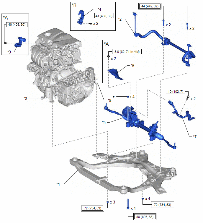
| *A | for A25A-FKS, A25A-FXS | *B | for AWD |
| *1 | FRONT FRAME ASSEMBLY | *2 | FRONT STABILIZER BAR WITH BRACKET |
| *3 | FUEL DELIVERY GUARD | *4 | FUEL PUMP PROTECTOR |
| *5 | RACK AND PINION POWER STEERING GEAR ASSEMBLY | *6 | STEERING GEAR HEAT INSULATOR |
| *7 | WIRE HARNESS | *8 | FRONT ENGINE MOUNTING INSULATOR |
| *9 | REAR ENGINE MOUNTING INSULATOR | - | - |
| | Tightening torque for "Major areas involving basic vehicle performance such as moving/turning/stopping": N*m (kgf*cm, ft.*lbf) | | N*m (kgf*cm, ft.*lbf): Specified torque |
| ● | Non-reusable part | - | - |
ILLUSTRATION
.png)
| *A | for 2GR-FKS | - | - |
| *1 | RACK AND PINION POWER STEERING GEAR ASSEMBLY | *2 | STEERING GEAR HEAT INSULATOR |
| *3 | TIE ROD ASSEMBLY LH | *4 | TIE ROD ASSEMBLY RH |
| | Tightening torque for "Major areas involving basic vehicle performance such as moving/turning/stopping": N*m (kgf*cm, ft.*lbf) | | N*m (kgf*cm, ft.*lbf): Specified torque |
ILLUSTRATION
.png)
| *1 | NO. 1 STEERING RACK BOOT | *2 | NO. 2 STEERING RACK BOOT |
| *3 | STEERING RACK BOOT CLAMP | *4 | STEERING RACK BOOT CLIP |
| ● | Non-reusable part | .png) | Lithium soap base glycol grease |
READ NEXT:
 Removal
REMOVAL CAUTION / NOTICE / HINT The necessary procedures (adjustment, calibration, initialization, or registration) that must be performed after parts are removed and installed, or replaced during rac
Disassembly
DISASSEMBLY PROCEDURE 1. REMOVE STEERING RACK BOOT CLIP (for LH Side) (a) Using pliers, remove the steering rack boot clip. 2. REMOVE STEERING RACK BOOT CLIP (for RH Side) HINT: Perform the same proce
Inspection
INSPECTION PROCEDURE 1. INSPECT TIE ROD ASSEMBLY LH (a) Secure the tie rod assembly LH in a vise between aluminum plates. NOTICE: Do not overtighten the vise. (b) Install the nut to the
SEE MORE:
Components
COMPONENTS ILLUSTRATION *1 LUGGAGE COMPARTMENT FLOOR MAT *2 SPARE WHEEL COVER TRAY ILLUSTRATION *1 REAR FLOOR FINISH PLATE *2 LUGGAGE HOLD BELT STRIKER ASSEMBLY ILLUSTRATION *A w/o Power Trunk Lid System *B w/ Power Trunk Lid System *C for Type A *D for
A25a-fks Oil And Oil Filter
Components
COMPONENTS
ILLUSTRATION
*1
CENTER NO. 4 ENGINE UNDER COVER
-
-
ILLUSTRATION
*1
OIL FILTER SUB-ASSEMBLY
*2
OIL FILLER CAP SUB-ASSEMBLY
*3
GASKET
