Lexus ES: Disassembly
DISASSEMBLY
PROCEDURE
1. REMOVE STEERING RACK BOOT CLIP (for LH Side)
(a) Using pliers, remove the steering rack boot clip.
2. REMOVE STEERING RACK BOOT CLIP (for RH Side)
HINT:
Perform the same procedure as for the LH side.
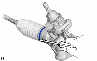
3. REMOVE STEERING RACK BOOT CLAMP (for LH Side)
| (a) Using a screwdriver, remove the steering rack boot clamp. NOTICE: Be careful not to damage the No. 2 steering rack boot. |
|
4. REMOVE STEERING RACK BOOT CLAMP (for RH Side)
HINT:
Perform the same procedure as for the LH side.
5. REMOVE NO. 2 STEERING RACK BOOT
(a) Remove the No. 2 steering rack boot.
NOTICE:
- Check that there is no water, foreign matter or rust inside of the removed No. 2 steering rack boot.
- If there is no water, foreign matter or rust inside of the No. 2 steering rack boot, pull out the rack bar and check for water, foreign matter or rust.
- If water or foreign matter in either part, replace them with a new rack and pinion power steering gear assembly.
- In order to avoid water or foreign matter from adhering to the parts, do not touch the parts unless working in a dust-free, indoors environment.
6. REMOVE NO. 1 STEERING RACK BOOT
HINT:
Perform the same procedure as for the No. 2 steering rack boot.
READ NEXT:
 Inspection
INSPECTION PROCEDURE 1. INSPECT TIE ROD ASSEMBLY LH (a) Secure the tie rod assembly LH in a vise between aluminum plates. NOTICE: Do not overtighten the vise. (b) Install the nut to the
Reassembly
REASSEMBLY PROCEDURE 1. INSTALL NO. 2 STEERING RACK BOOT (a) Apply lithium soap base glycol grease to the inside of the small opening of a new No. 2 steering rack boot. Lithium Soap Base Glycol
Installation
INSTALLATION PROCEDURE 1. INSTALL STEERING GEAR HEAT INSULATOR (for 2GR-FKS) (a) Install the steering gear heat insulator to the rack and pinion power steering gear assembly with the 2 bolts in the
SEE MORE:
Inspection
INSPECTION PROCEDURE 1. INSPECT PORT FUEL INJECTOR ASSEMBLY (a) Check the resistance. (1) Measure the resistance according to the value(s) in the table below. Standard Resistance: Tester Connection Condition Specified Condition 1 - 2 20°C (68°F) 11.6 to 12.4 Ω If the result
Rr Sensor Initialization Incomplete (C1AF4)
DESCRIPTION When it is judged that the rear sensors have not been initialized, the clearance warning ECU assembly stores DTC C1AF4. DTC No. Detection Item DTC Detection Condition Trouble Area C1AF4 Rr Sensor Initialization Incomplete Rear sensor not initialized
Initialize rear
© 2016-2026 Copyright www.lexguide.net
