Lexus ES: Lexus Safety System + 2.0
The Lexus Safety System + 2.0 consists of the following drive assist systems and contributes to a safe and comfortable driving experience:
Driving assist system
- PCS (Pre-Collision System)
- LTA (Lane Tracing Assist)
- Automatic High Beam
- RSA (Road Sign Assist) (if equipped)
- Dynamic radar cruise control with full-speed range
WARNING
■Lexus Safety System + 2.0 The Lexus Safety System + 2.0 is designed to operate under the assumption that the driver will drive safely, and is designed to help reduce the impact to the occupants and the vehicle in the case of a collision or assist the driver in normal driving conditions.
As there is a limit to the degree of recognition accuracy and control performance that this system can provide, do not overly rely on this system. The driver is always responsible for paying attention to the vehicle's surroundings and driving safely.
Sensors
Two types of sensors, located behind the front grille and windshield, detect information necessary to operate the drive assist systems.
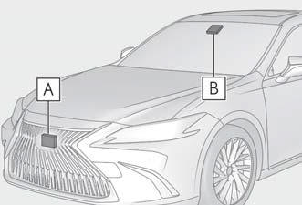
- Radar sensor
- Front camera
WARNING
■To avoid malfunction of the radar sensor Observe the following precautions.
Otherwise, the radar sensor may not operate properly, possibly leading to an accident resulting in death or serious injury.
- Keep the radar sensor and the grille cover clean at all times.
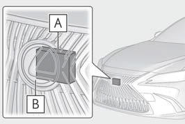
- Radar sensor
- Grille cover
If the front of the radar sensor or the front or back of the grille cover is dirty or covered with water droplets, snow, etc., clean it.
Clean the radar sensor and grille cover with a soft cloth to avoid damaging them.
- Do not attach accessories, stickers (including transparent stickers) or other items to the radar sensor, grille cover or surrounding area.
- Do not subject the radar sensor or its
surrounding area to a strong impact.
If the radar sensor, front grille, or front bumper has been subjected to a strong impact, have the vehicle inspected by your Lexus dealer.
- Do not disassemble the radar sensor.
- Do not modify or paint the radar sensor or grille cover.
- If the radar sensor, front grille, or front bumper needs to be removed and installed, or replaced, contact your Lexus dealer.
■To avoid malfunction of the front camera Observe the following precautions.
Otherwise, the front camera may not operate properly, possibly leading to an accident resulting in death or serious injury.
- Keep the windshield clean at all times.
- If the windshield is dirty or covered with an oily film, water droplets, snow, etc., clean the windshield.
- If a glass coating agent is applied to the windshield, it will still be necessary to use the windshield wipers to remove water droplets, etc. from the area of the windshield in front of the front camera.
- If the inner side of the windshield where the front camera is installed is dirty, contact your Lexus dealer.
- Do not attach objects, such as stickers, transparent stickers, etc., to the outer side of the windshield in front of the front camera (shaded area in the illustration).
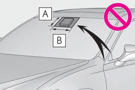
- From the top of the windshield to approximately 0.4 in. (1 cm) below the bottom of the front camera
- Approximately 7.9 in. (20 cm) (Approximately 4.0 in. [10 cm] to the right and left from the center of the front camera)
WARNING
- If the part of the windshield in front of the front camera is fogged up or covered with condensation, or ice, use the windshield defogger to remove the fog, condensation, or ice.
- If water droplets cannot be properly
removed from the area of the windshield
in front of the front camera by
the windshield wipers, replace the
wiper insert or wiper blade.
If the wiper inserts or wiper blades need to be replaced, contact your Lexus dealer.
- Do not attach window tint to the windshield.
- Replace the windshield if it is damaged
or cracked.
If the windshield needs to be replaced, contact your Lexus dealer.
- Do not allow liquids to contact the front camera.
- Do not allow bright lights to shine into the front camera.
- Do not dirty or damage the front camera.
When cleaning the inside of the windshield, do not allow glass cleaner to contact the lens of the front camera.
Also, do not touch the lens.
If the lens is dirty or damaged, contact your Lexus dealer.
- Do not subject the front camera to a strong impact.
- Do not change the installation position or direction of the front camera or remove it.
- Do not disassemble the front camera.
- Do not modify any components of the vehicle around the front camera (inside rear view mirror, etc.) or ceiling.
- Do not attach any accessories to the hood, front grille or front bumper that may obstruct the front camera. Contact your Lexus dealer for details.
- If a surfboard or other long object is to be mounted on the roof, make sure that it will not obstruct the front camera.
- Do not modify the headlights or other lights.
■If a warning message is displayed on the multi-information display A system may be temporarily unavailable or there may be a malfunction in the system.
- In the following situations, perform the actions specified in the table.
When the normal
operating conditions are detected, the message will disappear and the system
will
become operational.
If the message does not disappear, contact your Lexus dealer.
| Situation | Actions |
| When the area around a sensor is covered with dirt, moisture (fogged up, covered with condensation, ice, etc.), or other foreign matter | To clean the part of the windshield in front of the front camera, use the windshield wipers or the windshield defogger of the air conditioning system |
| When the temperature around the front camera is outside of the operational range, such as when the vehicle is in the sun or in an extremely cold environment | If the front camera is hot, such as after the
vehicle had been parked in the sun, use the
air conditioning system to decrease the temperature
around the front camera.
If a sunshade was used when the vehicle was parked, depending on its type, the sunlight reflected from the surface of the sunshade may cause the temperature of the front camera to become excessively high. |
| If the front camera is cold, such after the vehicle is parked in an extremely cold environment, use the air conditioning system to increase the temperature around the front camera. | |
| The area in front of the front camera is obstructed, such as when the hood is open or a sticker is attached to the part of the windshield in front of the front camera. | Close the hood, remove the sticker, etc. to clear the obstruction. |
- In the following situations, if the situation has changed (or the
vehicle has been driven for
some time) and the normal operating conditions are detected, the message
will disappear
and the system will become operational.
If the message does not disappear, contact your Lexus dealer.
- When the temperature around the radar sensor is outside of the operational range, such as when the vehicle is in the sun or in an extremely cold environment
- When the front camera cannot detect objects in front of the vehicle, such as when driving in the dark, snow, or fog, or when bright lights are shining into the front camera
READ NEXT:
 PCS (Pre-Collision System)
The pre-collision system uses a
radar sensor and front camera to
detect objects in front of
the vehicle. When the system
determines that the possibility of a
frontal collision with an object is
LTA (Lane Tracing Assist)
When driving on highways and
freeways with white (yellow) lane
lines, this function alerts the driver
when the vehicle might depart from
its lane or course* and provides
assistance by operating t
RSA (Road Sign Assist)
The RSA system recognizes specific
road signs using the front camera
to provide information to the
driver via the display.
If the system judges that the vehicle
is being driven over the speed l
SEE MORE:
Installation
INSTALLATION CAUTION / NOTICE / HINT NOTICE:
Before replacing the main body ECU (multiplex network body ECU), refer to Registration.
SMART ACCESS SYSTEM WITH PUSH-BUTTON START(for Start Function, Gasoline Model): Click here SMART ACCESS SYSTEM WITH PUSH-BUTTON START(for Start Function, HV Mod
Terminals Of Ecu
TERMINALS OF ECU CHECK PARKING BRAKE ECU (BRAKE ACTUATOR ASSEMBLY) *a Front view of wire harness connector (to Parking Brake ECU (Brake Actuator Assembly)) - - (a) Disconnect the A54 parking brake ECU (brake actuator assembly) connector. (b) Measure the voltage and resistance according
