Lexus ES: Components
COMPONENTS
ILLUSTRATION
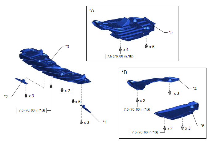
| *A | for A25A-FXS | *B | for 2GR-FKS |
| *1 | FRONT WHEEL OPENING EXTENSION PAD LH | *2 | FRONT WHEEL OPENING EXTENSION PAD RH |
| *3 | NO. 1 ENGINE UNDER COVER | *4 | NO. 2 ENGINE UNDER COVER |
| *5 | NO. 2 ENGINE UNDER COVER ASSEMBLY | *6 | NO. 3 ENGINE UNDER COVER |
.png) | N*m (kgf*cm, ft.*lbf): Specified torque | - | - |
ILLUSTRATION
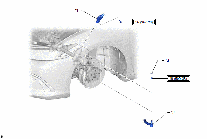
| *1 | STEERING INTERMEDIATE SHAFT ASSEMBLY | *2 | TIE ROD ASSEMBLY LH |
| *3 | COTTER PIN | - | - |
.png) | Tightening torque for "Major areas involving basic vehicle performance such as moving/turning/stopping": N*m (kgf*cm, ft.*lbf) | ● | Non-reusable part |
ILLUSTRATION
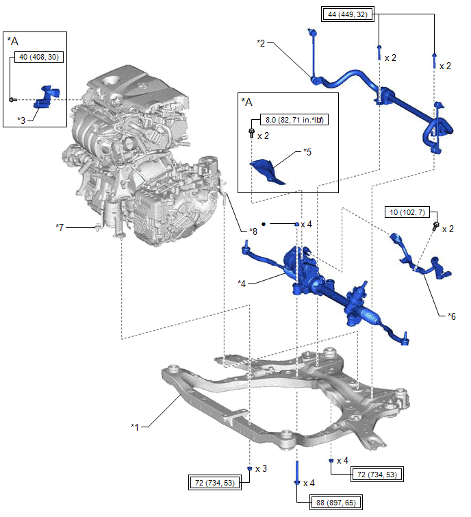
| *A | for A25A-FXS | - | - |
| *1 | FRONT FRAME ASSEMBLY | *2 | FRONT STABILIZER BAR WITH BRACKET |
| *3 | FUEL DELIVERY GUARD | *4 | RACK AND PINION POWER STEERING GEAR ASSEMBLY |
| *5 | STEERING GEAR HEAT INSULATOR | *6 | WIRE HARNESS |
| *7 | FRONT ENGINE MOUNTING INSULATOR | *8 | REAR ENGINE MOUNTING INSULATOR |
| | Tightening torque for "Major areas involving basic vehicle performance such as moving/turning/stopping": N*m (kgf*cm, ft.*lbf) | | N*m (kgf*cm, ft.*lbf): Specified torque |
| ● | Non-reusable part | - | - |
ILLUSTRATION
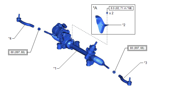
| *A | for 2GR-FKS | - | - |
| *1 | RACK AND PINION POWER STEERING GEAR ASSEMBLY | *2 | STEERING GEAR HEAT INSULATOR |
| *3 | TIE ROD ASSEMBLY LH | *4 | TIE ROD ASSEMBLY RH |
| | Tightening torque for "Major areas involving basic vehicle performance such as moving/turning/stopping": N*m (kgf*cm, ft.*lbf) | | N*m (kgf*cm, ft.*lbf): Specified torque |
ILLUSTRATION
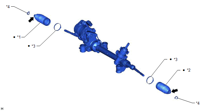
| *1 | NO. 1 STEERING RACK BOOT | *2 | NO. 2 STEERING RACK BOOT |
| *3 | STEERING RACK BOOT CLAMP | *4 | STEERING RACK BOOT CLIP |
| ● | Non-reusable part | .png) | Lithium soap base glycol grease |
READ NEXT:
 Components
COMPONENTS ILLUSTRATION *A for A25A-FKS, A25A-FXS *B for 2GR-FKS *1 FRONT WHEEL OPENING EXTENSION PAD LH *2 FRONT WHEEL OPENING EXTENSION PAD RH *3 NO. 1 ENGINE UNDER COVER
Removal
REMOVAL CAUTION / NOTICE / HINT The necessary procedures (adjustment, calibration, initialization, or registration) that must be performed after parts are removed and installed, or replaced during rac
Disassembly
DISASSEMBLY PROCEDURE 1. REMOVE STEERING RACK BOOT CLIP (for LH Side) (a) Using pliers, remove the steering rack boot clip. 2. REMOVE STEERING RACK BOOT CLIP (for RH Side) HINT: Perform the same proce
SEE MORE:
Removal
REMOVAL
CAUTION / NOTICE / HINT
The necessary procedures (adjustment, calibration, initialization, or registration)
that must be performed after parts are removed and installed, or replaced during
front brake flexible hose removal/installation are shown below.
Necessary Procedures After Parts
Removal
REMOVAL CAUTION / NOTICE / HINT The necessary procedures (adjustment, calibration, initialization or registration) that must be performed after parts are removed and installed, or replaced during fuel tank pressure sensor (vapor pressure sensor assembly) removal/installation are shown below. Necessa
