Lexus ES: Inspection
INSPECTION
PROCEDURE
1. INSPECT HV BATTERY JUNCTION BLOCK ASSEMBLY
(a) Inspect SMRB:
(1) Measure the resistance according to the value(s) in the table below.
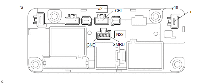
| *a | Component without harness connected (HV Battery Junction Block Assembly) | - | - |
Standard Resistance:
| Tester Connection | Condition | Specified Condition |
|---|---|---|
| y18-1 (+) - a2-1 (CBI) | Auxiliary battery voltage not applied between terminals N22-1 (SMRB) and N22-3 (GND) | 10 kΩ or higher |
| Auxiliary battery voltage applied between terminals N22-1 (SMRB) and N22-3 (GND) | Below 1 Ω |
(2) Measure the resistance according to the value(s) in the table below.
Standard Resistance:
| Tester Connection | Condition | Specified Condition |
|---|---|---|
| N22-1 (SMRB) - N22-3 (GND) | -40 to 80°C (-40 to 176°F) | 19.0 to 59.0 Ω |
If the result is not as specified, replace the HV battery junction block assembly.
(b) Inspect SMRG:
(1) Measure the resistance according to the value(s) in the table below.
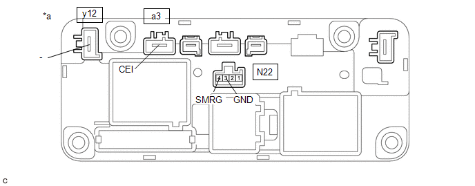
| *a | Component without harness connected (HV Battery Junction Block Assembly) | - | - |
Standard Resistance:
| Tester Connection | Condition | Specified Condition |
|---|---|---|
| y12-1 (-) - a3-1 (CEI) | Auxiliary battery voltage not applied between terminals N22-4 (SMRG) and N22-3 (GND) | 10 kΩ or higher |
| Auxiliary battery voltage applied between terminals N22-4 (SMRG) and N22-3 (GND) | Below 1 Ω |
(2) Measure the resistance according to the value(s) in the table below.
Standard Resistance:
| Tester Connection | Condition | Specified Condition |
|---|---|---|
| N22-4 (SMRG) - N22-3 (GND) | -40 to 80°C (-40 to 176°F) | 19.0 to 59.0 Ω |
If the result is not as specified, replace the HV battery junction block assembly.
(c) Inspect SMRP:
(1) Measure the resistance according to the value(s) in the table below.
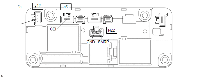
| *a | Component without harness connected (HV Battery Junction Block Assembly) | - | - |
Standard Resistance:
| Tester Connection | Condition | Specified Condition |
|---|---|---|
| y12-1 (-) - a3-1 (CEI) | Auxiliary battery voltage not applied between terminals N22-2 (SMRP) and N22-3 (GND) | 10 kΩ or higher |
| Auxiliary battery voltage applied between terminals N22-2 (SMRP) and N22-3 (GND) | 24.3 to 29.7 Ω |
(2) Measure the resistance according to the value(s) in the table below.
Standard Resistance:
| Tester Connection | Condition | Specified Condition |
|---|---|---|
| N22-2 (SMRP) - N22-3 (GND) | -40 to 80°C (-40 to 176°F) | 140 to 290 Ω |
If the result is not as specified, replace the HV battery junction block assembly.
READ NEXT:
 Installation
INSTALLATION PROCEDURE 1. INSTALL HV BATTERY JUNCTION BLOCK ASSEMBLY CAUTION: Be sure to wear insulated gloves and protective goggles. (a) Install the HV battery junction block assembly to the HV batt
Definition Of Terms
DEFINITION OF TERMS Term Definition Monitor Description Description of what the battery ECU assembly monitors and how to detects malfunctions (monitoring purpose and its details). Relat
SEE MORE:
Installation
INSTALLATION PROCEDURE 1. INSTALL INVERTER WATER PUMP ASSEMBLY (a) Connect the No. 2 inverter cooling hose and No. 3 inverter cooling hose to the inverter water pump assembly and slide the 2 clips to secure them. NOTICE:
Make sure to align the alignment marks of the hoses with the ribs of th
Diagnosis System
DIAGNOSIS SYSTEM DESCRIPTION (a) The hybrid vehicle control ECU has a self-diagnosis system. If the computer, hybrid control system, or a component is not working properly, the ECU records the conditions that relate to the fault. The ECU also illuminates the master warning light in the combination m
