Lexus ES: Removal
REMOVAL
CAUTION / NOTICE / HINT
The necessary procedures (adjustment, calibration, initialization, or registration) that must be performed after parts are removed and installed, or replaced during ultrasonic sensor removal/installation are shown below.
Necessary Procedure After Parts Removed/Installed/Replaced (for HV Model)| Replaced Part or Performed Procedure | Necessary Procedure | Effect/Inoperative Function When Necessary Procedures are not Performed | Link |
|---|---|---|---|
|
*1: w/ Hands Free Power Trunk Lid
*2: When performing learning using the Techstream. Click here | |||
| Disconnect cable from negative auxiliary battery terminal*1 | Perform steering sensor zero point calibration | Lane Control System | |
| Pre-collision System | |||
| Parking Support Brake System*2 | |||
| Lighting System | |||
| Memorize steering angle neutral point | Parking Assist Monitor System | | |
| Panoramic View Monitor System | | ||
| Initialize power trunk lid system | Power Trunk Lid System | | |
|
|
| |
NOTICE:
- After the power switch is turned off, the radio receiver assembly records various types of memory and settings. As a result, after turning the power switch off, make sure to wait at least 85 seconds before disconnecting the cable from the negative (-) auxiliary battery terminal. (for Audio and Visual System)
- After the power switch is turned off, the radio receiver assembly records various types of memory and settings. As a result, after turning the power switch off, make sure to wait at least 85 seconds before disconnecting the cable from the negative (-) auxiliary battery terminal. (for Navigation System)
| Replaced Part or Performed Procedure | Necessary Procedure | Effect/Inoperative Function When Necessary Procedures are not Performed | Link |
|---|---|---|---|
|
*1: w/ Hands Free Power Trunk Lid
*2: When performing learning using the Techstream. Click here | |||
| Disconnect cable from negative battery terminal*1 | Perform steering sensor zero point calibration | Lane Control System | |
| Pre-collision System | |||
| Parking Support Brake System*2 | |||
| Lighting System | |||
| Memorize steering angle neutral point | Parking Assist Monitor System | | |
| Panoramic View Monitor System | | ||
| Initialize power trunk lid system | Power Trunk Lid System | | |
|
|
| |
NOTICE:
- After the engine switch is turned off, the radio receiver assembly records various types of memory and settings. As a result, after turning the engine switch off, make sure to wait at least 85 seconds before disconnecting the cable from the negative (-) battery terminal. (for Audio and Visual System)
- After the engine switch is turned off, the radio receiver assembly records various types of memory and settings. As a result, after turning the engine switch off, make sure to wait at least 85 seconds before disconnecting the cable from the negative (-) battery terminal. (for Navigation System)
PROCEDURE
1. REMOVE REAR BUMPER ASSEMBLY
for Single Type: Click here .gif)
for Dual Type: Click here
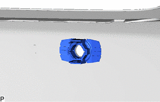
2. REMOVE REAR CENTER ULTRASONIC SENSOR
HINT:
The illustration is for the LH side. Use the same procedure for the RH side and LH side.
(a) Disconnect the connector.
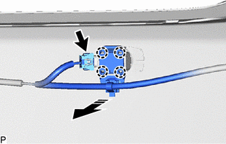
.png) | Remove in this Direction |
(b) Disengage the 4 claws as shown in the illustration.
(c) Disengage the 2 claws and remove the rear center ultrasonic sensor as shown in the illustration.
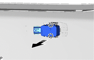
| | Remove in this Direction |
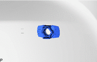
3. REMOVE REAR CORNER ULTRASONIC SENSOR
HINT:
The illustration is for the LH side. The orientation for the RH side is the opposite of the LH side.
(a) Disconnect the connector.
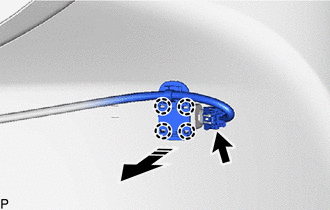
| | Remove in this Direction |
(b) Disengage the 4 claws as shown in the illustration.
(c) Disengage the 2 claws and remove the rear corner ultrasonic sensor as shown in the illustration.
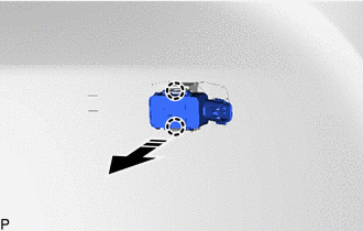
| | Remove in this Direction |
4. REMOVE ULTRASONIC SENSOR CLIP
HINT:
- Perform this procedure only when replacement of the ultrasonic sensor clip is necessary.
- Use the same procedure for all ultrasonic sensor clips.
| (a) Disengage the clamp to remove the ultrasonic sensor clip from the wire. |
|
.png)
5. REMOVE REAR CENTER ULTRASONIC SENSOR RETAINER
HINT:
- Perform this procedure only when replacement of the rear center ultrasonic sensor retainer is necessary.
- When removing the rear center ultrasonic sensor retainer, heat the rear bumper assembly and rear center ultrasonic sensor retainer using a heat light.
- The illustration is for the LH side. Use the same procedure for the RH side and LH side.
(a) Heat the rear bumper assembly and rear center ultrasonic sensor retainer using a heat light at the specified temperature for 3 to 5 minutes.
Heating Temperature:
| Item | Temperature |
|---|---|
| Rear Bumper Assembly | 40 to 60°C (104 to 140°F) |
| Rear Center Ultrasonic Sensor Retainer |
CAUTION:
- Do not touch the heat light and heated parts.
- Touching the heat light may result in burns.
- Touching heated parts for a long time may result in burns.
.png)
| *a | Heated Part |
| *b | Heat Light |
| (b) Remove the rear center ultrasonic sensor retainer. |
|
6. REMOVE REAR CORNER ULTRASONIC SENSOR RETAINER
HINT:
- Perform this procedure only when replacement of the rear corner ultrasonic sensor retainer is necessary.
- When removing the rear corner ultrasonic sensor retainer, heat the rear bumper assembly and rear corner ultrasonic sensor retainer using a heat light.
- The illustration is for the LH side. Use the same procedure for the RH side and LH side.
(a) Heat the rear bumper assembly and rear corner ultrasonic sensor retainer using a heat light at the specified temperature for 3 to 5 minutes.
Heating Temperature:
| Item | Temperature |
|---|---|
| Rear Bumper Assembly | 40 to 60°C (104 to 140°F) |
| Rear Corner Ultrasonic Sensor Retainer |
CAUTION:
- Do not touch the heat light and heated parts.
- Touching the heat light may result in burns.
- Touching heated parts for a long time may result in burns.
| *a | Heated Part |
| *b | Heat Light |
| (b) Remove the rear corner ultrasonic sensor retainer. |
|
7. REMOVE ULTRASONIC SENSOR CUSHION SET
HINT:
Only perform this procedure when removing and installing the ultrasonic sensor cushion set.
(a) Remove the ultrasonic sensor cushion set as shown in the illustration.
.png)
| | Remove in this Direction | - | - |
READ NEXT:
 Data List / Active Test
DATA LIST / ACTIVE TEST DATA LIST NOTICE: In the table below, the values listed under "Normal Condition" are reference values. Do not depend solely on these reference values when deciding whether a pa
SEE MORE:
Rr Sensor Initialization Incomplete (C1AF4)
DESCRIPTION When it is judged that the rear sensors have not been initialized, the clearance warning ECU assembly stores DTC C1AF4. DTC No. Detection Item DTC Detection Condition Trouble Area C1AF4 Rr Sensor Initialization Incomplete Rear sensor not initialized
Initialize rear
EVAP System
RELATED DTCS DTC No. SAE Monitoring Item Link P00FE00 P00FE EVAP vent line blocked P043E00 P043E Reference orifice clogged (built into canister pump module) P043F00 P043F Reference orifice high-flow (built into canister pump module) P04417E P0441 Pu
