Lexus ES: Components
COMPONENTS
ILLUSTRATION
.png)
| *1 | BATTERY SERVICE HOLE COVER | *2 | SERVICE PLUG GRIP |
ILLUSTRATION
.png)
| *1 | CONNECTOR COVER ASSEMBLY | *2 | ENGINE ROOM MAIN WIRE |
.png) | Tightening torque for "Major areas involving basic vehicle performance such as moving/turning/stopping": N*m (kgf*cm, ft.*lbf) | .png) | N*m (kgf*cm, ft.*lbf): Specified torque |
ILLUSTRATION
.png)
| *1 | REAR UNDER COVER | *2 | REAR UNDER SIDE COVER LH |
| *3 | REAR UNDER SIDE COVER RH | *4 | REAR SEAT CUSHION LEG SUB-ASSEMBLY |
| *5 | REAR SEAT CUSHION ASSEMBLY | *6 | REAR DOOR SCUFF PLATE LH |
| *7 | REAR DOOR SCUFF PLATE RH | *8 | REAR SEAT CUSHION LOCK HOOK |
| *9 | REAR CENTER SEAT OUTER BELT ASSEMBLY | *10 | REAR SEAT INNER BELT ASSEMBLY RH |
| *11 | WASHER | - | - |
| | Tightening torque for "Major areas involving basic vehicle performance such as moving/turning/stopping": N*m (kgf*cm, ft.*lbf) | ● | Non-reusable part |
ILLUSTRATION
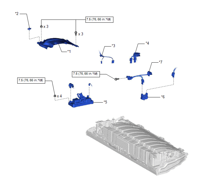
| *1 | NO. 1 HV BATTERY COVER PANEL RH | *2 | BATTERY COVER LOCK STRIKER |
| *3 | FLOOR WIRE | *4 | HV FLOOR UNDER WIRE |
| *5 | HV BATTERY JUNCTION BLOCK ASSEMBLY | *6 | HYBRID BATTERY TERMINAL BLOCK |
| *7 | ELECTRIC VEHICLE BATTERY PLUG ASSEMBLY | - | - |
| | N*m (kgf*cm, ft.*lbf): Specified torque | - | - |
READ NEXT:
 Inspection
INSPECTION PROCEDURE 1. INSPECT HYBRID BATTERY TERMINAL BLOCK (a) Measure the resistance according to the value(s) in the table below. Standard Resistance: Tester Connection Condition Speci
Installation
INSTALLATION PROCEDURE 1. INSTALL HYBRID BATTERY TERMINAL BLOCK CAUTION: Be sure to wear insulated gloves and protective goggles. (a) Engage the claw to install the hybrid battery terminal block to th
SEE MORE:
Hybrid/EV Battery Sensor Module Internal Electronic Failure (P0AFC49)
DTC SUMMARY MALFUNCTION DESCRIPTION When the hybrid control system is activated, the hybrid vehicle control ECU checks the power supply voltage of the battery voltage sensor and detects malfunction. The cause of this malfunction may be one of the following: Battery voltage sensor internal malfuncti
Data List / Active Test
DATA LIST / ACTIVE TEST DATA LIST HINT: Using the Techstream to read the Data List allows the values or states of switches, sensors, actuators and other items to be read without removing any parts. This non-intrusive inspection can be very useful because intermittent conditions or signals may be dis
