Lexus ES: Components
COMPONENTS
ILLUSTRATION
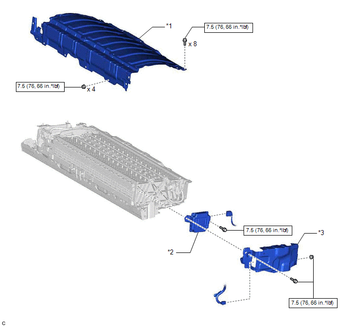
| *1 | UPPER HV BATTERY COVER SUB-ASSEMBLY | *2 | BATTERY VOLTAGE SENSOR |
| *3 | NO. 1 HV BATTERY SHIELD PANEL | - | - |
.png) | N*m (kgf*cm, ft.*lbf): Specified torque | - | - |
READ NEXT:
 Removal
REMOVAL CAUTION / NOTICE / HINT The necessary procedures (adjustment, calibration, initialization or registration) that must be performed after parts are removed and installed, or replaced during batt
Installation
INSTALLATION PROCEDURE 1. INSTALL BATTERY VOLTAGE SENSOR CAUTION: Be sure to wear insulated gloves and protective goggles. (a) Install the battery voltage sensor to the HV battery with the bolt. To
Combination Switch
ComponentsCOMPONENTS ILLUSTRATION *1 EV DRIVE MODE SWITCH (NO. 3 COMBINATION SWITCH ASSEMBLY) - - InspectionINSPECTION PROCEDURE 1. INSPECT EV DRIVE MODE SWITCH (NO. 3 COMBINATION SWITC
SEE MORE:
Adjustment
ADJUSTMENT CAUTION / NOTICE / HINT The necessary procedures (adjustment, calibration, initialization or registration) that must be performed after parts are removed and installed, or replaced during automatic transaxle fluid replacement are shown below. Necessary Procedures After Parts Removed/Insta
CAN Communication Failure (Message Registry) (U1000)
DESCRIPTION When the clearance warning ECU assembly determines that the CAN communication circuit is malfunctioning during self diagnosis, DTC U1000 is stored. DTC No. Detection Item DTC Detection Condition Trouble Area U1000 CAN Communication Failure (Message Registry) CAN communic
© 2016-2026 Copyright www.lexguide.net
