Lexus ES: Components
COMPONENTS
ILLUSTRATION
.png)
| *1 | BATTERY SERVICE HOLE COVER | *2 | SERVICE PLUG GRIP |
ILLUSTRATION
.png)
| *1 | CONNECTOR COVER ASSEMBLY | *2 | ENGINE ROOM MAIN WIRE |
.png) | Tightening torque for "Major areas involving basic vehicle performance such as moving/turning/stopping": N*m (kgf*cm, ft.*lbf) | .png) | N*m (kgf*cm, ft.*lbf): Specified torque |
ILLUSTRATION
.png)
| *1 | REAR UNDER COVER | *2 | REAR UNDER SIDE COVER LH |
| *3 | REAR UNDER SIDE COVER RH | *4 | REAR SEAT CUSHION LEG SUB-ASSEMBLY |
| *5 | REAR SEAT CUSHION ASSEMBLY | *6 | REAR DOOR SCUFF PLATE LH |
| *7 | REAR DOOR SCUFF PLATE RH | *8 | REAR SEAT CUSHION LOCK HOOK |
| *9 | REAR CENTER SEAT OUTER BELT ASSEMBLY | *10 | REAR SEAT INNER BELT ASSEMBLY RH |
| *11 | WASHER | - | - |
| | Tightening torque for "Major areas involving basic vehicle performance such as moving/turning/stopping": N*m (kgf*cm, ft.*lbf) | ● | Non-reusable part |
ILLUSTRATION
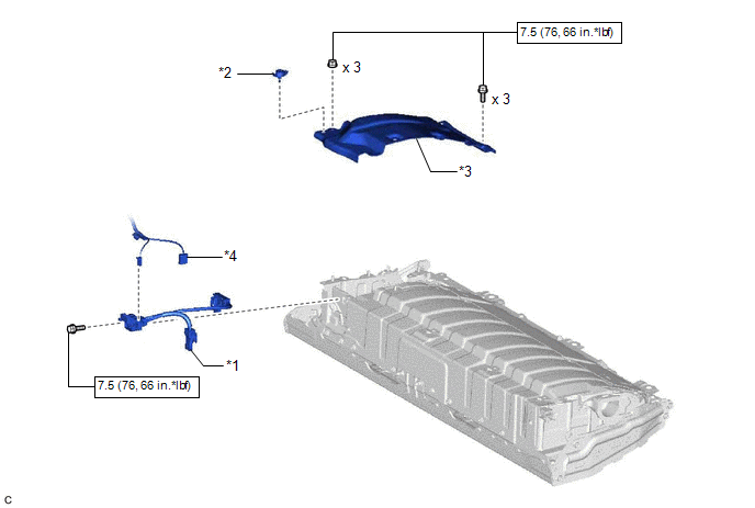
| *1 | ELECTRIC VEHICLE BATTERY PLUG ASSEMBLY | *2 | BATTERY COVER LOCK STRIKER |
| *3 | NO. 1 HV BATTERY COVER PANEL RH | *4 | FLOOR WIRE |
| | N*m (kgf*cm, ft.*lbf): Specified torque | - | - |
READ NEXT:
 Inspection
INSPECTION PROCEDURE 1. INSPECT ELECTRIC VEHICLE BATTERY PLUG ASSEMBLY (a) Measure the resistance according to the value(s) in the table below. Standard Resistance: Tester Connection Conditio
Installation
INSTALLATION PROCEDURE 1. INSTALL ELECTRIC VEHICLE BATTERY PLUG ASSEMBLY CAUTION: Be sure to wear insulated gloves and protective goggles. (a) Install the electric vehicle battery plug assembly to the
SEE MORE:
Intake Air Control Valve(for Acis)
On-vehicle InspectionON-VEHICLE INSPECTION PROCEDURE 1. INSPECT INTAKE AIR CONTROL VALVE (for ACIS) (a) Disconnect the vacuum hose sub-assembly from the intake air control valve (for ACIS). (b) Connect a hose and vacuum pump to the intake air control valve (for ACIS). (c) Using th
Removal
REMOVAL PROCEDURE 1. REMOVE NO. 1 INSTRUMENT PANEL UNDER COVER SUB-ASSEMBLY Click here 2. REMOVE ACCELERATOR PEDAL(W/SENSOR) ROD ASSEMBLY NOTICE:
Avoid physical shock to the accelerator pedal sensor assembly.
Do not disassemble the accelerator pedal sensor assembly.
The accelerator pedal s
