Lexus ES: Removal
REMOVAL
PROCEDURE
1. REMOVE NO. 1 INSTRUMENT PANEL UNDER COVER SUB-ASSEMBLY
Click here .gif)
2. REMOVE ACCELERATOR PEDAL(W/SENSOR) ROD ASSEMBLY
NOTICE:
- Avoid physical shock to the accelerator pedal sensor assembly.
- Do not disassemble the accelerator pedal sensor assembly.
- The accelerator pedal sensor assembly does not require lubrication.
- Do not apply oil or other lubricants to the accelerator pedal sensor assembly. If applied, the accelerator pedal sensor assembly must be replaced.
| (a) Disconnect the accelerator pedal sensor assembly connector. |
|
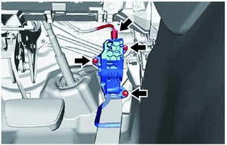
(b) Remove the 3 nuts and disconnect the rod of the accelerator pedal sensor assembly from the accelerator pedal assembly to remove the accelerator pedal sensor assembly.
NOTICE:
If the accelerator pedal sensor assembly has been struck or dropped, replace it.
3. REMOVE ACCELERATOR PEDAL PAD
| (a) Disengage the 4 claws and remove the accelerator pedal pad from the accelerator pedal assembly. |
|
.png)
4. REMOVE ACCELERATOR PEDAL ASSEMBLY
| (a) Remove the 2 bolts. |
|
.png)
(b) Push the accelerator pedal assembly in the direction indicated by the arrow (1) shown in the illustration to disengage the claw.
.png)
| *a | Vehicle Body |
.png) | Remove in this Direction (1) |
.png) | Remove in this Direction (2) |
(c) Pull the accelerator pedal assembly in the direction indicated by the arrow (2) shown in the illustration to remove it.
READ NEXT:
 Installation
INSTALLATION PROCEDURE 1. INSTALL ACCELERATOR PEDAL ASSEMBLY (a) Engage the claw to install the accelerator pedal assembly. (b) Install the 2 bolts. Torque: 7.5 N·m {76 kgf·cm, 66 in
Components
COMPONENTS ILLUSTRATION *1 REAR UNDER COVER *2 REAR UNDER SIDE COVER LH *3 REAR UNDER SIDE COVER RH *4 REAR SEAT CUSHION LEG SUB-ASSEMBLY *5 REAR SEAT CUSHION ASSEMBLY *6
SEE MORE:
System Description
SYSTEM DESCRIPTION GENERAL (a) The rear window defogger wire (back window glass) is attached to the inside of the rear window and defogs the window surface quickly when the rear window defogger switch is pressed. The indicator light on the switch illuminates while the system is operating. This syste
Diagnosis System
DIAGNOSIS SYSTEM PARKING ASSIST MONITOR SYSTEM DIAGNOSTIC MODE (a) In diagnostic mode for the parking assist monitor system, signals received by the radio receiver assembly can be checked and the parking assist monitor system can be calibrated, adjusted and checked using the multi-display assembly.
