Lexus ES: Components
COMPONENTS
ILLUSTRATION
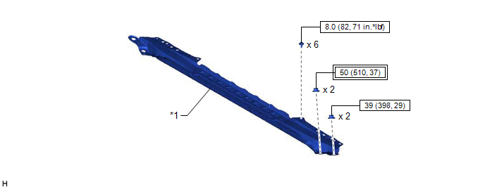
| *1 | FRONT CENTER UPPER SUSPENSION BRACE SUB-ASSEMBLY | - | - |
.png) | Tightening torque for "Major areas involving basic vehicle performance such as moving/turning/stopping" : N*m (kgf*cm, ft.*lbf) | .png) | N*m (kgf*cm, ft.*lbf): Specified torque |
ILLUSTRATION
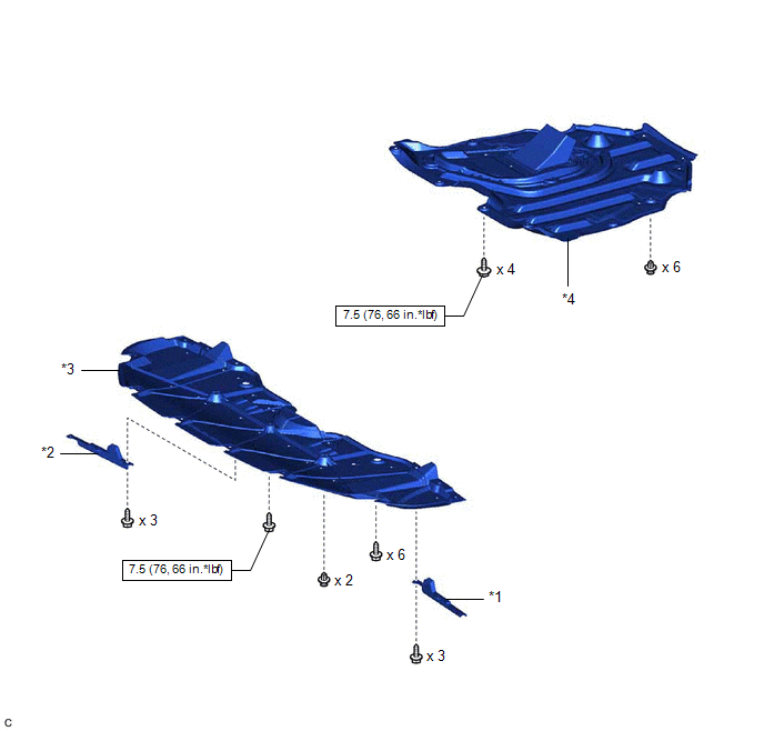
| *1 | FRONT WHEEL OPENING EXTENSION PAD LH | *2 | FRONT WHEEL OPENING EXTENSION PAD RH |
| *3 | NO. 1 ENGINE UNDER COVER | *4 | NO. 2 ENGINE UNDER COVER ASSEMBLY |
| | N*m (kgf*cm, ft.*lbf): Specified torque | - | - |
ILLUSTRATION
.png)
| *A | Type A | *B | Type B |
| *1 | FRONT FLOOR COVER RH | - | - |
| | N*m (kgf*cm, ft.*lbf): Specified torque | - | - |
ILLUSTRATION
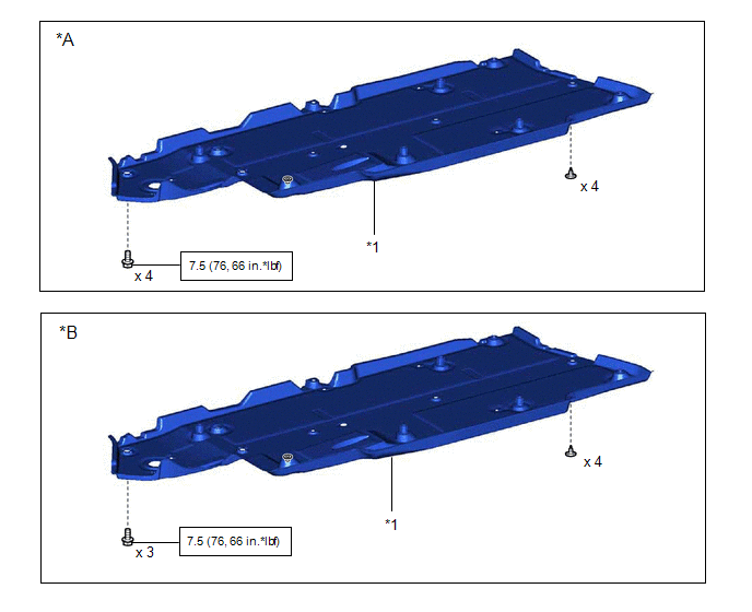
| *A | Type A | *B | Type B |
| *1 | FRONT FLOOR COVER LH | - | - |
| | N*m (kgf*cm, ft.*lbf): Specified torque | - | - |
ILLUSTRATION
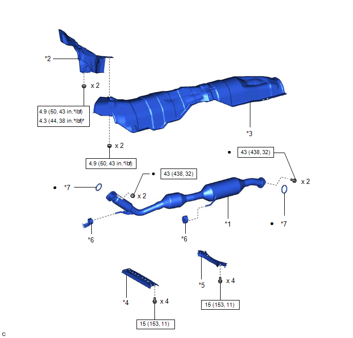
| *1 | FRONT EXHAUST PIPE ASSEMBLY (TWC: Rear Catalyst) | *2 | NO. 1 UPPER FRONT FLOOR HEAT INSULATOR |
| *3 | FRONT LOWER NO. 1 FLOOR HEAT INSULATOR | *4 | CENTER FLOOR CROSSMEMBER BRACE |
| *5 | FRONT CENTER FLOOR BRACE | *6 | EXHAUST PIPE SUPPORT |
| *7 | GASKET | - | - |
| | N*m (kgf*cm, ft.*lbf): Specified torque | * | For use with a union nut wrench |
| ● | Non-reusable part | - | - |
ILLUSTRATION
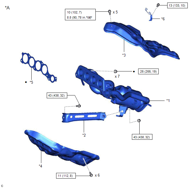
| *A | Type A | - | - |
| *1 | EXHAUST MANIFOLD (TWC: Front Catalyst) | *2 | MANIFOLD STAY |
| *3 | NO. 1 EXHAUST MANIFOLD HEAT INSULATOR | *4 | NO. 2 EXHAUST MANIFOLD HEAT INSULATOR |
| *5 | EXHAUST MANIFOLD TO HEAD GASKET | *6 | WIRE HARNESS CLAMP BRACKET |
| | N*m (kgf*cm, ft.*lbf): Specified torque | * | For use with a union nut wrench |
| ● | Non-reusable part | - | - |
ILLUSTRATION
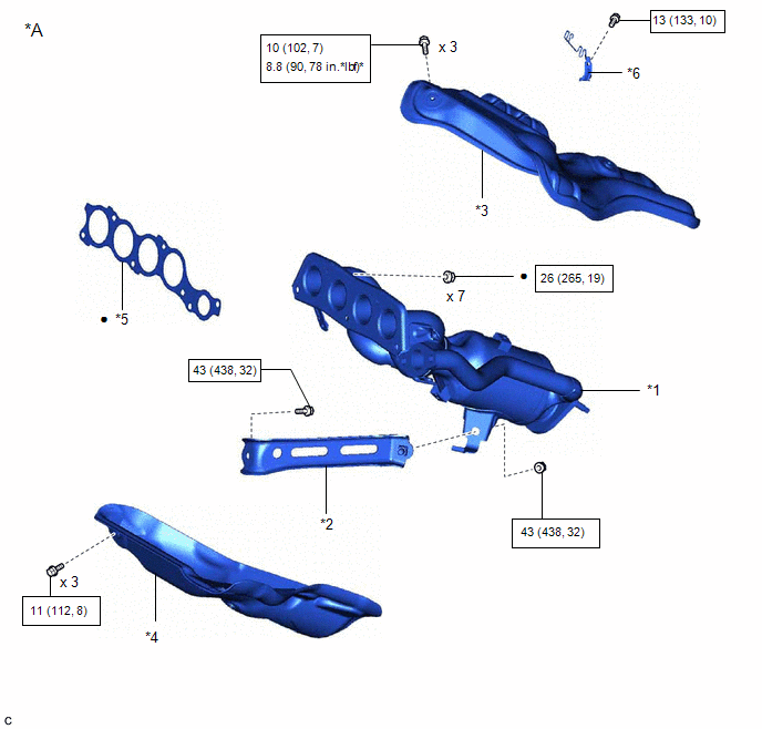
| *A | Type B | - | - |
| *1 | EXHAUST MANIFOLD | *2 | MANIFOLD STAY |
| *3 | NO. 1 EXHAUST MANIFOLD HEAT INSULATOR | *4 | NO. 2 EXHAUST MANIFOLD HEAT INSULATOR |
| *5 | EXHAUST MANIFOLD TO HEAD GASKET | *6 | WIRE HARNESS CLAMP BRACKET |
| | N*m (kgf*cm, ft.*lbf): Specified torque | * | For use with a union nut wrench |
| ● | Non-reusable part | - | - |
READ NEXT:
 Removal
REMOVAL CAUTION / NOTICE / HINT The necessary procedures (adjustment, calibration, initialization or registration) that must be performed after parts are removed and installed, or replaced during exha
Installation
INSTALLATION PROCEDURE 1. INSTALL NO. 2 EXHAUST MANIFOLD HEAT INSULATOR (a) Type A: (1) Install the No. 2 exhaust manifold heat insulator to the exhaust manifold (TWC: Front Catalyst) with the 6 bolts
SEE MORE:
Inspection
INSPECTION PROCEDURE 1. INSPECT CONNECTING ROD THRUST CLEARANCE (a) Install the connecting rod cap. Click here (b) Using a dial indicator, measure the thrust clearance while moving the connecting rod back and forth. Standard Thrust Clearance: 0.15 to 0.40 mm (0.00591 to 0.0157 in.) Maximum Thr
Luggage Compartment Door Closer does not Operate
DESCRIPTION The luggage compartment door closer operation controls the luggage door closer assembly via the luggage closer motor assembly based on switch signals in the luggage door closer assembly. WIRING DIAGRAM CAUTION / NOTICE / HINT NOTICE:
Check that B2250 or B2251 is not output before pro
