Lexus ES: Components
Lexus ES (XZ10) Service Manual / Audio & Visual & Telematics / Audio / Video / Amplifier Antenna / Components
COMPONENTS
ILLUSTRATION
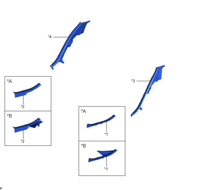
| *A | for HV Model | *B | for Gasoline Model |
| *1 | REAR DOOR SCUFF PLATE LH | *2 | REAR DOOR SCUFF PLATE RH |
| *3 | REAR SEAT SIDE GARNISH LH | *4 | REAR SEAT SIDE GARNISH RH |
ILLUSTRATION
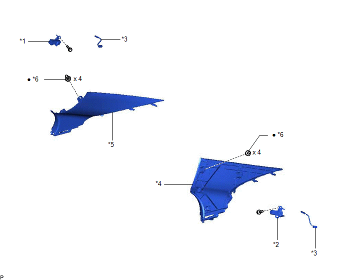
| *1 | NO. 1 AMPLIFIER ANTENNA ASSEMBLY | *2 | NO. 2 AMPLIFIER ANTENNA ASSEMBLY |
| *3 | NO. 4 ANTENNA CORD SUB-ASSEMBLY | *4 | ROOF SIDE INNER GARNISH ASSEMBLY LH |
| *5 | ROOF SIDE INNER GARNISH ASSEMBLY RH | *6 | CLIP |
| ● | Non-reusable part | - | - |
READ NEXT:
 Installation
INSTALLATION PROCEDURE 1. INSTALL NO. 4 ANTENNA CORD SUB-ASSEMBLY (a) Connect the connector to install the No. 4 antenna cord sub-assembly. HINT: Use the same procedure for the RH side and LH side. 2.
Removal
REMOVAL CAUTION / NOTICE / HINT The necessary procedures (adjustment, calibration, initialization, or registration) that must be performed after parts are removed and installed, or replaced during amp
SEE MORE:
How To Proceed With Troubleshooting
CAUTION / NOTICE / HINT HINT:
Use the following procedure to troubleshoot the parking assist monitor system.
*: Use the Techstream.
PROCEDURE 1. VEHICLE BROUGHT TO WORKSHOP
NEXT 2. CUSTOMER PROBLEM ANALYSIS (a) Ask the customer about the problems and the co
A/F (O2) Sensor Circuit Bank 1 Sensor 2 Circuit Current (Voltage) Below Threshold (P013616,P013A7C)
DESCRIPTION Refer to DTC P003612. Click here HINT: Although the DTC title say O2 sensor, this DTC relate to the air fuel ratio sensor (sensor 2). DTC No. Detection Item DTC Detection Condition Trouble Area MIL Memory Note P013616 A/F (O2) Sensor Circuit Bank 1 Sensor 2 Circuit
© 2016-2026 Copyright www.lexguide.net
