Lexus ES: Removal
REMOVAL
CAUTION / NOTICE / HINT
The necessary procedures (adjustment, calibration, initialization, or registration) that must be performed after parts are removed and installed, or replaced during amplifier antenna assembly removal/installation are shown below.
Necessary Procedure After Parts Removed/Installed/Replaced (for HV Model)| Replaced Part or Performed Procedure | Necessary Procedures | Effect/Inoperative Function When Necessary Procedures are not Performed | Link |
|---|---|---|---|
|
*: When performing learning using the Techstream.
Click here | |||
| Disconnect cable from negative auxiliary battery terminal | Perform steering sensor zero point calibration | Lane Control System | |
| Pre-collision System | |||
| Parking Support Brake System* | |||
| Lighting System | |||
| Memorize steering angle neutral point | Parking Assist Monitor System | | |
| Panoramic View Monitor System | | ||
| Initialize power trunk lid system | Power Trunk Lid System | | |
CAUTION:
Some of these service operations affect the SRS airbag system. Read the precautionary notices concerning the SRS airbag system before servicing.
.png)
Click here .gif)
NOTICE:
- After the power switch is turned off, the radio receiver assembly records various types of memory and settings. As a result, after turning the power switch off, make sure to wait at least 85 seconds before disconnecting the cable from the negative (-) auxiliary battery terminal. (for Audio and Visual System)
- After the power switch is turned off, the radio receiver assembly records various types of memory and settings. As a result, after turning the power switch off, make sure to wait at least 85 seconds before disconnecting the cable from the negative (-) auxiliary battery terminal. (for Navigation System)
| Replaced Part or Performed Procedure | Necessary Procedures | Effect/Inoperative Function When Necessary Procedures are not Performed | Link |
|---|---|---|---|
|
*: When performing learning using the Techstream.
Click here | |||
| Disconnect cable from negative battery terminal | Perform steering sensor zero point calibration | Lane Control System | |
| Pre-collision System | |||
| Parking Support Brake System* | |||
| Lighting System | |||
| Memorize steering angle neutral point | Parking Assist Monitor System | | |
| Panoramic View Monitor System | | ||
| Initialize power trunk lid system | Power Trunk Lid System | | |
CAUTION:
Some of these service operations affect the SRS airbag system. Read the precautionary notices concerning the SRS airbag system before servicing.
Click here
NOTICE:
- After the engine switch is turned off, the radio receiver assembly records various types of memory and settings. As a result, after turning the engine switch off, make sure to wait at least 85 seconds before disconnecting the cable from the negative (-) battery terminal. (for Audio and Visual System)
- After the engine switch is turned off, the radio receiver assembly records various types of memory and settings. As a result, after turning the engine switch off, make sure to wait at least 85 seconds before disconnecting the cable from the negative (-) battery terminal. (for Navigation System)
PROCEDURE
1. REMOVE REAR SEAT ASSEMBLY
Click here
2. REMOVE REAR DOOR SCUFF PLATE LH (for HV Model)
Click here
3. REMOVE REAR DOOR SCUFF PLATE LH (for Gasoline Model)
Click here
4. REMOVE REAR DOOR SCUFF PLATE RH (for HV Model)
HINT:
Use the same procedure as for the LH side.
5. REMOVE REAR DOOR SCUFF PLATE RH (for Gasoline Model)
HINT:
Use the same procedure as for the LH side.
6. REMOVE REAR SEAT SIDE GARNISH LH
Click here
7. REMOVE REAR SEAT SIDE GARNISH RH
HINT:
Use the same procedure as for the LH side.
8. REMOVE ROOF SIDE INNER GARNISH ASSEMBLY LH
Click here
9. REMOVE ROOF SIDE INNER GARNISH ASSEMBLY RH
HINT:
Use the same procedure as for the LH side.
10. REMOVE NO. 2 AMPLIFIER ANTENNA ASSEMBLY
| (a) Disconnect the 2 connectors. |
|
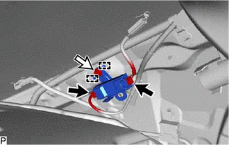
(b) Remove the bolt.
(c) Disengage the 2 guides to remove the No. 2 amplifier antenna assembly.
11. REMOVE NO. 1 AMPLIFIER ANTENNA ASSEMBLY
HINT:
Use the same procedure as for the No. 2 amplifier antenna assembly.
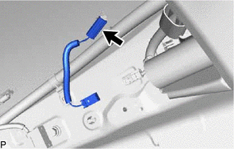
12. REMOVE NO. 4 ANTENNA CORD SUB-ASSEMBLY
| (a) Disconnect the connector to remove the No. 4 antenna cord sub-assembly. HINT: Use the same procedure for the RH side and LH side. |
|
READ NEXT:
 AVC-LAN Circuit
DESCRIPTION Each unit of the audio and visual system connected to the AVC-LAN (communication bus) transmits signals via AVC-LAN communication. If a short to +B or short to ground occurs in an AVC-LAN
Stereo Component Amplifier Malfunction (B15A3)
DESCRIPTION This DTC is stored when a malfunction occurs in the stereo component amplifier assembly. DTC No. Detection Item DTC Detection Condition Trouble Area B15A3 Stereo Component A
SEE MORE:
Diagnosis System
DIAGNOSIS SYSTEM DIAGNOSIS FUNCTION (a) The diagnosis function turns off the cruise control indicator, illuminates the master warning light and displays a warning message when a malfunction is detected. When a malfunction is detected in the dynamic radar cruise control system, DTCs are stored in the
Installation
INSTALLATION CAUTION / NOTICE / HINT HINT:
Use the same procedure for the RH side and LH side.
The following procedure is for the LH side.
PROCEDURE 1. INSTALL HOOD SUPPORT BRACKET (a) Engage the guide. (b) Install the hood support bracket with the bolt. Torque: 17.5 N·m {178 kgf·cm, 13 f
