Lexus ES: Components
Lexus ES (XZ10) Service Manual / Engine & Hybrid System / A25a-fks (starting) / Starter / Components
COMPONENTS
ILLUSTRATION
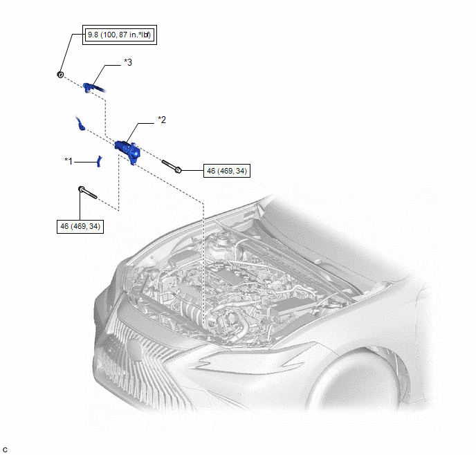
| *1 | FLYWHEEL HOUSING SIDE COVER | *2 | STARTER ASSEMBLY |
| *3 | NO. 2 ENGINE WIRE | - | - |
.png) | Tightening torque for "Major areas involving basic vehicle performance such as moving/turning/stopping": N*m (kgf*cm, ft.*lbf) | .png) | N*m (kgf*cm, ft.*lbf): Specified torque |
ILLUSTRATION
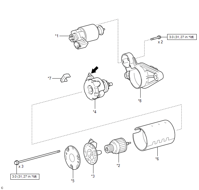
| *1 | MAGNET STARTER SWITCH ASSEMBLY | *2 | STARTER ARMATURE ASSEMBLY |
| *3 | STARTER BRUSH HOLDER ASSEMBLY | *4 | STARTER CENTER BEARING CLUTCH SUB-ASSEMBLY |
| *5 | STARTER COMMUTATOR END FRAME ASSEMBLY | *6 | STARTER YOKE ASSEMBLY |
| *7 | RUBBER SEAL | *8 | STARTER DRIVE HOUSING ASSEMBLY |
| | N*m (kgf*cm, ft.*lbf): Specified torque | .png) | High-temperature Grease |
READ NEXT:
 Disassembly
DISASSEMBLY PROCEDURE 1. REMOVE MAGNET STARTER SWITCH ASSEMBLY (a) Remove the 2 bolts. (b) While lifting the rear of the magnet starter switch assembly disconnect it from terminal C.
Inspection
INSPECTION PROCEDURE 1. INSPECT STARTER ASSEMBLY CAUTION: As a large electric current passes through the cable during this inspection, a thick cable must be used. If not, the cable may become hot and
Reassembly
REASSEMBLY PROCEDURE 1. INSTALL STARTER CENTER BEARING CLUTCH SUB-ASSEMBLY (a) Apply high-temperature grease to the pinion drive lever. High-temperature Grease HINT: Apply approximately 0.1
SEE MORE:
Speaker Circuit (B1350)
DESCRIPTION The vehicle approaching speaker assembly circuit consists of the vehicle approaching speaker controller and vehicle approaching speaker assembly. This DTC is stored when a malfunction is detected in the vehicle approaching speaker assembly circuit or vehicle approaching speaker controlle
Clearance Warning ECU Communication Stop Mode
DESCRIPTION Detection Item Symptom Trouble Area Clearance Warning ECU Communication Stop Mode Any of the following conditions are met:
Communication stop for "Clearance Warning (Intuitive Parking Assist)" is indicated on the "Communication Bus Check" screen of the Techstream.
Click h
© 2016-2026 Copyright www.lexguide.net
