Lexus ES: Components
Lexus ES (XZ10) Service Manual / Engine & Hybrid System / A25a-fks (emission Control) / Canister / Components
COMPONENTS
ILLUSTRATION
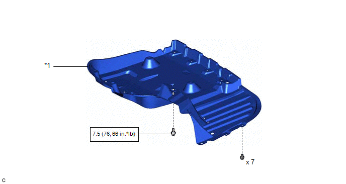
| *1 | REAR FLOOR SIDE MEMBER COVER | - | - |
.png) | N*m (kgf*cm, ft.*lbf): Specified torque | - | - |
ILLUSTRATION
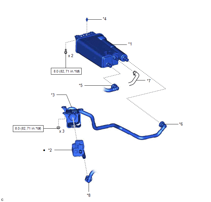
| *1 | CANISTER (CHARCOAL CANISTER ASSEMBLY) | *2 | LEAK DETECTION PUMP SUB-ASSEMBLY |
| *3 | NO. 2 CHARCOAL CANISTER SUB-ASSEMBLY | *4 | CLIP |
| *5 | FUEL TANK VENT HOSE | *6 | VENT LINE HOSE |
| *7 | PURGE LINE HOSE | *8 | AIR LINE TUBE |
| | N*m (kgf*cm, ft.*lbf): Specified torque | ● | Non-reusable part |
READ NEXT:
 Removal
REMOVAL PROCEDURE 1. REMOVE REAR FLOOR SIDE MEMBER COVER (a) Remove the bolt and 7 clips. (b) Disengage the 3 clamps (A) and 2 clamps (B) to remove the rear floor side member cover from
Inspection
INSPECTION PROCEDURE 1. INSPECT CANISTER (CHARCOAL CANISTER ASSEMBLY) (a) Visually check the canister (charcoal canister assembly). (1) Visually check the canister (charcoal canister assembly) for
Installation
INSTALLATION PROCEDURE 1. INSTALL LEAK DETECTION PUMP SUB-ASSEMBLY HINT: Only perform this procedure when replacement of the leak detection pump sub-assembly is necessary. (a) Engage the 2 claws to
SEE MORE:
Components
COMPONENTS ILLUSTRATION *1 ENGINE WIRE *2 NO. 1 VACUUM HOSE CONNECTOR *3 VACUUM PUMP ASSEMBLY *4 NO. 1 VACUUM PUMP O-RING Tightening torque for "Major areas involving basic vehicle performance such as moving/turning/stopping": N*m (kgf*cm, ft.*lbf) ● Non-reusable par
ECM/PCM Power Relay Sense Circuit Intermittent (P06881F)
DESCRIPTION This DTC indicates that the hybrid vehicle control ECU detected an instantaneous interruption in +B power source voltage. DTC No. Detection Item DTC Detection Condition Trouble Area MIL Warning Indicate P06881F ECM/PCM Power Relay Sense Circuit Intermittent When the
© 2016-2026 Copyright www.lexguide.net
