Lexus ES: ECM/PCM Power Relay Sense Circuit Intermittent (P06881F)
DESCRIPTION
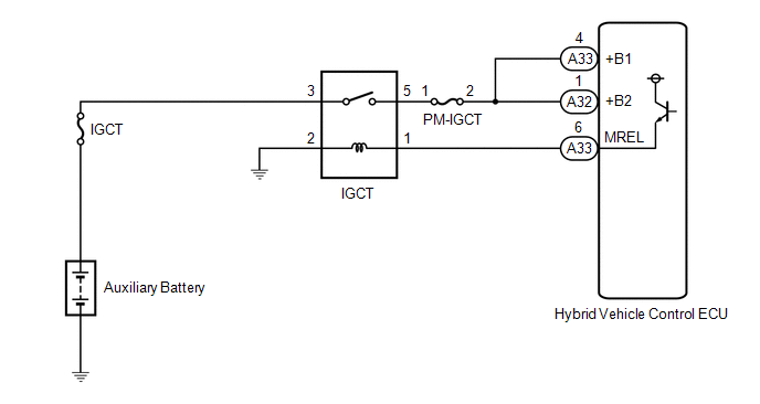
This DTC indicates that the hybrid vehicle control ECU detected an instantaneous interruption in +B power source voltage.
| DTC No. | Detection Item | DTC Detection Condition | Trouble Area | MIL | Warning Indicate |
|---|---|---|---|---|---|
| P06881F | ECM/PCM Power Relay Sense Circuit Intermittent | When the power switch is on (READY), the hybrid vehicle control ECU is reset due to an instantaneous interruption of power source. (1 trip detection logic) |
| Does not come on | Master Warning Light: Comes on |
CONFIRMATION DRIVING PATTERN
HINT:
After repair has been completed, clear the DTCs and then check that the vehicle has returned to normal by performing the following All Readiness check procedure.
Click here .gif)
- Connect the Techstream to the DLC3.
- Turn the power switch on (IG) and turn the Techstream on.
- Clear the DTCs (even if no DTCs are stored, perform the clear DTC procedure).
- Turn the power switch off and wait for 2 minutes or more.
- Turn the power switch on (IG) and turn the Techstream on.
-
Turn the power switch on (READY) and wait for 30 seconds or more.
(If the DTC is not output, drive the vehicle on urban roads according to the freeze frame data item "Vehicle Speed" for approximately 5 minutes.)
- Enter the following menus: Powertrain / Hybrid Control / Utility / All Readiness.
-
Check the DTC judgment result.
HINT:
- If the judgment result shows NORMAL, the system is normal.
- If the judgment result shows ABNORMAL, the system has a malfunction.
- If the judgment result shows INCOMPLETE or N/A, perform driving pattern again.
WIRING DIAGRAM
PROCEDURE
| 1. | CHECK AUXILIARY BATTERY TERMINAL |
(a) Confirm whether the auxiliary battery terminals have been disconnected recently.
| Result | Proceed to |
|---|---|
| Terminals have been disconnected. | A |
| Terminals have not been disconnected. | B |
| B | .gif) | GO TO STEP 5 |
|
.gif)
| 2. | CONFIRM MASTER WARNING LIGHT |
(a) Turn the power switch on (READY) from off.
(b) Confirm that the master warning light illuminates.
| Result | Proceed to |
|---|---|
| Master warning light illuminates. | A |
| Master warning light does not illuminate. | B |
NOTICE:
DTC P06881F may be stored after disconnecting and reconnecting the auxiliary battery terminals. If this happens, the DTC will not be output if the power switch is turned off and then on (READY) again. In this case, clear the DTCs to complete the inspection.
(c) Turn the power switch off.
| B | | END |
|
| 3. | CLEAR DTC |
(a) Connect the Techstream to the DLC3.
(b) Turn the power switch on (IG).
(c) Enter the following menus: Powertrain / Hybrid Control / Trouble Codes.
(d) Read and record the DTCs and freeze frame data.
Powertrain > Hybrid Control > Trouble Codes(e) Clear the DTCs and freeze frame data.
Powertrain > Hybrid Control > Clear DTCs(f) Turn the power switch off and wait for 2 minutes or more.
|
| 4. | CHECK DTC OUTPUT (HYBRID CONTROL) |
(a) Connect the Techstream to the DLC3.
(b) Turn the power switch on (IG).
(c) Enter the following menus: Powertrain / Hybrid Control / Trouble Codes.
(d) Check for DTCs.
Powertrain > Hybrid Control > Trouble Codes| Result | Proceed to |
|---|---|
| DTC P06881F is output again. | A |
| DTCs other than P06881F are also output. | B |
(e) Turn the power switch off.
| B | | GO TO DTC CHART (HYBRID CONTROL SYSTEM) |
|
| 5. | CHECK AUXILIARY BATTERY TERMINAL (CONTACT PROBLEM) |
(a) Check the connection of the auxiliary battery terminal.
OK:
The terminal is connected securely and there is no contact problem.
| NG | | CONNECT SECURELY |
|
| 6. | CHECK CONNECTOR CONNECTION CONDITION (HYBRID VEHICLE CONTROL ECU CONNECTOR) |
Click here
| NG | | CONNECT SECURELY |
|
| 7. | CHECK HARNESS AND CONNECTOR (HYBRID VEHICLE CONTROL ECU - IGCT RELAY) |
(a) Remove the IGCT relay from the No. 3 relay block.
(b) Disconnect the A32 and A33 hybrid vehicle control ECU connectors.
(c) Measure the resistance according to the value(s) in the table below.
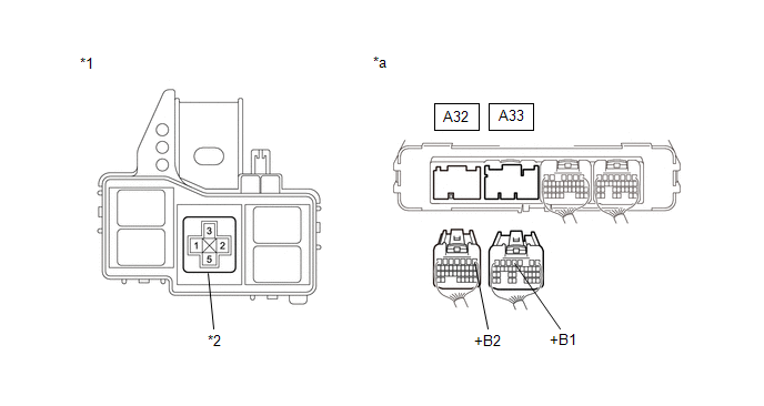
| *1 | No. 3 Relay Block | *2 | IGCT Relay Holder |
| *a | Rear view of wire harness connector (to Hybrid Vehicle Control ECU) | - | - |
Standard Resistance:
| Tester Connection | Condition | Specified Condition |
|---|---|---|
| A33-4 (+B1) - 5 (IGCT relay holder) | Power switch off | Below 1 Ω |
| A32-1 (+B2) - 5 (IGCT relay holder) | Power switch off | Below 1 Ω |
(d) Reconnect the A32 and A33 hybrid vehicle control ECU connectors.
(e) Reinstall the IGCT relay.
| NG | | REPAIR OR REPLACE HARNESS OR CONNECTOR |
|
| 8. | CHECK FOR INTERMITTENT PROBLEMS |
(a) Check for intermittent problems.
Click here
(1) Check the connection and terminal contact pressure of the connectors and wire harnesses between the hybrid vehicle control ECU and the No. 3 relay block.
(2) When the power switch is on (READY), jiggle the connectors and wire harnesses between the hybrid vehicle control ECU and the No. 3 relay block.
| Result | Proceed to |
|---|---|
| Problem symptom does not recur. | A |
| Problem symptom recurs. | B |
| A | | REPLACE HYBRID VEHICLE CONTROL ECU |
| B | | REPAIR OR REPLACE MALFUNCTIONING PARTS, COMPONENT AND AREA |
READ NEXT:
 Transmission Range Sensor "A" Circuit (PRNDL Input) Signal Compare Failure (P070562)
DESCRIPTION The shift lever position sensor sends 7 different switch signals to the hybrid vehicle control ECU. The hybrid vehicle control ECU uses these signals to detect the shift lever position (P,
High Voltage System Interlock Circuit Open (P0A0A13,P0A0A92)
DTC SUMMARY MALFUNCTION DESCRIPTION The hybrid vehicle control ECU detects that a safety device (interlock) is operated or that there is an open circuit in the detection circuit. (Even if an open circ
Drive Motor "A" Control Module Internal Electronic Failure (P0A1B49)
DESCRIPTION The motor generator control ECU (MG ECU), which is built into the inverter with converter assembly, monitors its internal operation and will store DTCs if the system is malfunctioning.
SEE MORE:
On-vehicle Inspection
ON-VEHICLE INSPECTION PROCEDURE 1. INSPECT WINDSHIELD WIPER MOTOR ASSEMBLY (a) for RH Side (1) Operate the windshield wiper motor assembly. (2) Stop the windshield wiper motor assembly operation. (3) Check the automatic stop (park) position. HINT: After the front wiper motor is stopped, check the
System Description
SYSTEM DESCRIPTION POWER MIRROR CONTROL SYSTEM (w/o Memory) DESCRIPTION (a) This system has the following functions: electrical remote control mirror function, power retract mirror function, mirror heater function and automatic glare-resistant EC mirror function. FUNCTION OF MAIN COMPONENT Compon
