Lexus ES: Removal
REMOVAL
PROCEDURE
1. REMOVE REAR FLOOR SIDE MEMBER COVER
| (a) Remove the bolt and 7 clips. |
|
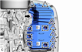
(b) Disengage the 3 clamps (A) and 2 clamps (B) to remove the rear floor side member cover from the vehicle body.
2. REMOVE CANISTER (CHARCOAL CANISTER ASSEMBLY)
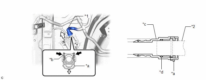
(a) Disconnect the fuel tank vent hose from the canister (charcoal canister assembly).
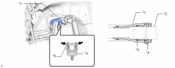
| *1 | Fuel Tank Vent Hose | *2 | Pipe (Canister (Charcoal Canister Assembly)) |
| *a | Retainer | *b | Tab |
| *c | Tube Connector | *d | O-ring |
.png) | Pinch | .png) | Pull |
NOTICE:
- Remove any dirt or foreign matter on the tube connector before performing this work.
- Do not allow any scratches or foreign matter to get on the parts when disconnecting them as the tube connector has an O-ring that seals the pipe (canister (charcoal canister assembly)).
- Perform this work by hand. Do not use any tools.
- Do not forcibly bend, twist or turn the fuel tank vent hose.
- Protect the disconnected parts by covering them with plastic bags after disconnecting the fuel tank vent hose.
- If the tube connector and pipe (canister (charcoal canister assembly)) are stuck, push and pull to release them.
HINT:
Do not remove the retainer.
(1) Pinch the tabs of the retainer to disengage the lock claws and pull it down.
(2) Pull off the fuel tank vent hose.
(b) Disconnect the vent line hose from the canister (charcoal canister assembly).
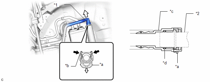
| *1 | Vent Line Hose | *2 | Pipe (Canister (Charcoal Canister Assembly)) |
| *a | Retainer | *b | Tab |
| *c | Tube Connector | *d | O-ring |
| | Pinch | | Pull |
NOTICE:
- Remove any dirt or foreign matter on the tube connector before performing this work.
- Do not allow any scratches or foreign matter to get on the parts when disconnecting them as the tube connector has an O-ring that seals the pipe (canister (charcoal canister assembly)).
- Perform this work by hand. Do not use any tools.
- Do not forcibly bend, twist or turn the vent line hose.
- Protect the disconnected parts by covering them with plastic bags after disconnecting the vent line hose.
- If the tube connector and pipe (canister (charcoal canister assembly)) are stuck, push and pull to release them.
HINT:
Do not remove the retainer.
(1) Pinch the tabs of the retainer to disengage the lock claws and pull it down.
(2) Pull off the vent line hose.
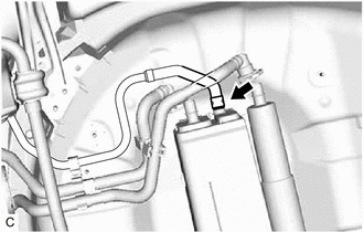
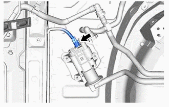
| (c) Slide the clip and disconnect the purge line hose from the canister (charcoal canister assembly). |
|
| (d) Remove the 2 bolts. |
|
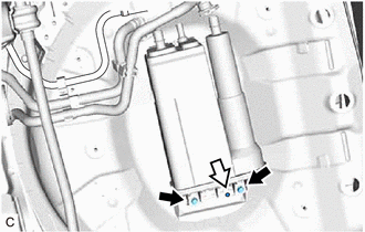
(e) Disengage the clip from the canister (charcoal canister assembly).
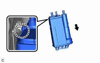
| (f) Disengage the claw and remove the canister (charcoal canister assembly) from vehicle body as shown in the illustration. |
|
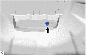
| (g) Remove the clip from the vehicle body. |
|
3. REMOVE NO. 2 CHARCOAL CANISTER SUB-ASSEMBLY
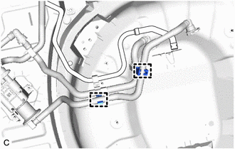
| (a) Disengage the 2 clamps. |
|
(b) Disconnect the air line tube from the leak detection pump sub-assembly.
| *1 | Air Line Tube | *2 | Pipe (Leak Detection Pump Sub-assembly) |
| *a | Retainer | *b | Tab |
| *c | Tube Connector | *d | O-ring |
| | Pinch | | Pull |
NOTICE:
- Remove any dirt or foreign matter on the tube connector before performing this work.
- Do not allow any scratches or foreign matter to get on the parts when disconnecting them as the tube connector has an O-ring that seals the pipe (leak detection pump sub-assembly).
- Perform this work by hand. Do not use any tools.
- Do not forcibly bend, twist or turn the air line tube.
- Protect the disconnected parts by covering them with plastic bags after disconnecting the air line tube.
- If the tube connector and pipe (leak detection pump sub-assembly) are stuck, push and pull to release them.
HINT:
Do not remove the retainer.
(1) Pinch the tabs of the retainer to disengage the lock claws and pull it down.
(2) Pull off the air line tube.
| (c) Disconnect the leak detection pump sub-assembly connector. |
|
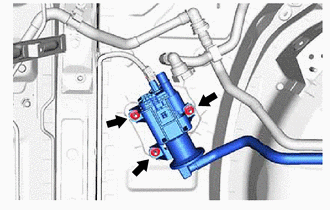
| (d) Remove the 3 nuts and No. 2 charcoal canister sub-assembly from the vehicle body. |
|
4. REMOVE LEAK DETECTION PUMP SUB-ASSEMBLY
HINT:
Only perform this procedure when replacement of the leak detection pump sub-assembly is necessary.
(a) Before removing the leak detection pump sub-assembly, clean the No. 2 charcoal canister sub-assembly by blowing air into it to ensure that the No. 2 charcoal canister sub-assembly is free of foreign matter.
NOTICE:
- Make sure to clean the No. 2 charcoal canister sub-assembly using air only.
- Do not use gasoline, thinners or solvents.
| (b) While disengaging the 2 claws as shown in the illustration, push the leak detection pump sub-assembly upwards using a screwdriver with its tip wrapped with protective tape to remove it. |
|
.png)
(c) Check if the No. 2 charcoal canister sub-assembly contains foreign matter such as mud or water.
| (1) Visually check that the inside of the No. 2 charcoal canister sub-assembly is free of foreign matter. |
|
.png)
(2) Hold the No. 2 charcoal canister sub-assembly upside down to make sure that it is free of foreign matter.
If the No. 2 charcoal canister sub-assembly contains foreign matter, replace it.
READ NEXT:
 Inspection
INSPECTION PROCEDURE 1. INSPECT CANISTER (CHARCOAL CANISTER ASSEMBLY) (a) Visually check the canister (charcoal canister assembly). (1) Visually check the canister (charcoal canister assembly) for
Installation
INSTALLATION PROCEDURE 1. INSTALL LEAK DETECTION PUMP SUB-ASSEMBLY HINT: Only perform this procedure when replacement of the leak detection pump sub-assembly is necessary. (a) Engage the 2 claws to
Egr Valve
InspectionINSPECTION PROCEDURE 1. INSPECT EGR VALVE ASSEMBLY (a) Measure the resistance according to the value(s) in the table below. Standard Resistance: Tester Connection Condition Speci
SEE MORE:
Components
COMPONENTS ILLUSTRATION *A for Power Tilt and Power Telescopic Steering Column - - *1 STEERING WHEEL SWITCH HOUSING *2 TILT AND TELESCOPIC SWITCH *3 TURN SIGNAL SWITCH *4 WINDSHIELD WIPER SWITCH ASSEMBLY
Components
COMPONENTS ILLUSTRATION *A Type A - - *1 EXHAUST MANIFOLD (TWC: Front Catalyst) *2 NO. 1 EXHAUST MANIFOLD HEAT INSULATOR *3 MANIFOLD STAY *4 EXHAUST MANIFOLD TO HEAD GASKET N*m (kgf*cm, ft.*lbf): Specified torque ● Non-reusable part ILLUSTRATION *A
