Lexus ES: Components
COMPONENTS
ILLUSTRATION
.png)
| *A | Type A | *B | Type B |
| *1 | FRONT FLOOR COVER RH | - | - |
.png) | N*m (kgf*cm, ft.*lbf): Specified torque | - | - |
ILLUSTRATION
.png)
| *A | Type A | *B | Type B |
| *1 | FRONT FLOOR COVER LH | - | - |
| | N*m (kgf*cm, ft.*lbf): Specified torque | - | - |
ILLUSTRATION
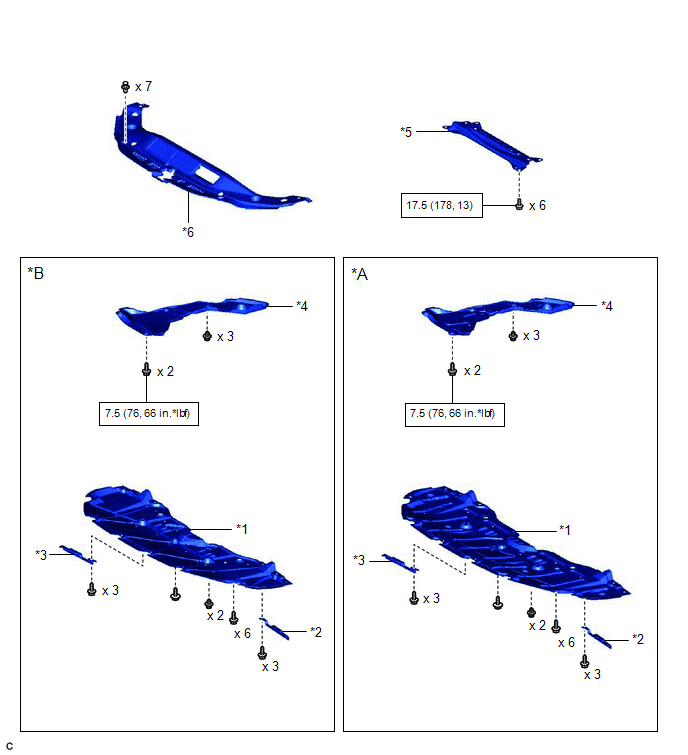
| *A | Type A | *B | Type B |
| *1 | NO. 1 ENGINE UNDER COVER | *2 | FRONT WHEEL OPENING EXTENSION PAD LH |
| *3 | FRONT WHEEL OPENING EXTENSION PAD RH | *4 | NO. 2 ENGINE UNDER COVER |
| *5 | BODY MOUNTING PLATE | *6 | COOL AIR INTAKE DUCT SEAL |
| | N*m (kgf*cm, ft.*lbf): Specified torque | - | - |
ILLUSTRATION
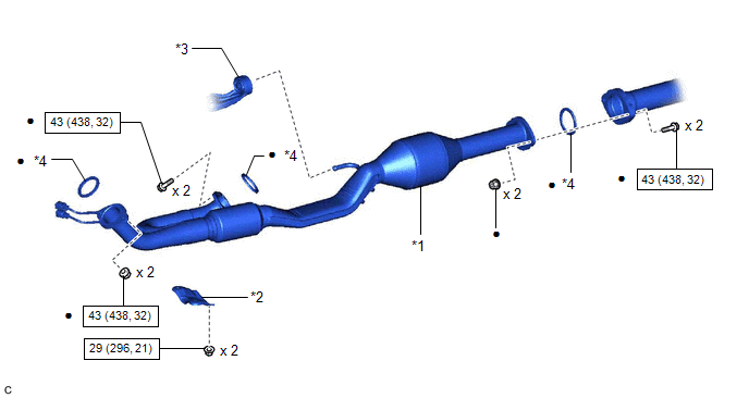
| *1 | FRONT EXHAUST PIPE ASSEMBLY (TWC: Rear Catalyst) | *2 | NO. 1 EXHAUST PIPE SUPPORT BRACKET (for Lower Side) |
| *3 | EXHAUST PIPE SUPPORT | *4 | GASKET |
| | N*m (kgf*cm, ft.*lbf): Specified torque | ● | Non-reusable part |
ILLUSTRATION
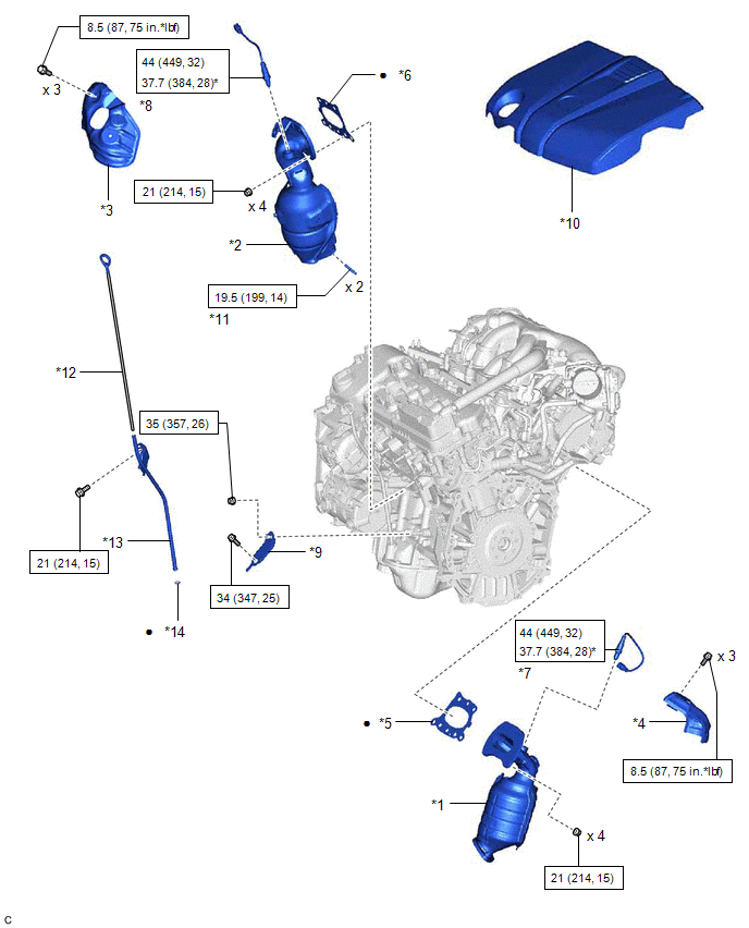
| *1 | EXHAUST MANIFOLD ASSEMBLY RH (TWC: Front Catalyst) | *2 | EXHAUST MANIFOLD ASSEMBLY LH (TWC: Front Catalyst) |
| *3 | NO. 2 EXHAUST MANIFOLD HEAT INSULATOR | *4 | NO. 1 EXHAUST MANIFOLD HEAT INSULATOR |
| *5 | EXHAUST MANIFOLD TO HEAD GASKET (for Bank 1) | *6 | EXHAUST MANIFOLD TO HEAD GASKET (for Bank 2) |
| *7 | AIR FUEL RATIO SENSOR (for Bank 1) | *8 | AIR FUEL RATIO SENSOR (for Bank 2) |
| *9 | NO. 2 MANIFOLD STAY | *10 | V-BANK COVER SUB-ASSEMBLY |
| *11 | STUD BOLT | *12 | ENGINE OIL LEVEL DIPSTICK |
| *13 | ENGINE OIL LEVEL DIPSTICK GUIDE | *14 | ENGINE OIL LEVEL DIPSTICK GUIDE O-RING |
| | N*m (kgf*cm, ft.*lbf): Specified torque | * | For use with SST |
| ● | Non-reusable part | - | - |
READ NEXT:
 Removal
REMOVAL CAUTION / NOTICE / HINT The necessary procedures (adjustment, calibration, initialization or registration) that must be performed after parts are removed and installed, or replaced during exha
Installation
INSTALLATION PROCEDURE 1. INSTALL STUD BOLT HINT: If a stud bolt is deformed or its threads are damaged, replace it. (a) Using an E8 "TORX" socket wrench, install the 2 stud bolts to the exhaust ma
SEE MORE:
Disc cannot be Ejected
CAUTION / NOTICE / HINT NOTICE:
Depending on the parts that are replaced during vehicle inspection or maintenance, performing initialization, registration or calibration may be needed. Refer to Precaution for Navigation System.
Click here
When replacing the radio receiver assembly, always re
Inspection
INSPECTION PROCEDURE 1. INSPECT LUGGAGE DOOR OPENING CANCEL SWITCH ASSEMBLY (a) Check the resistance. (1) Measure the resistance according to the value(s) in the table below. Standard Resistance: Tester Connection Switch Condition Specified Condition 2 (B) - 1 (L) Switch on Below
