Lexus ES: Removal
REMOVAL
CAUTION / NOTICE / HINT
The necessary procedures (adjustment, calibration, initialization or registration) that must be performed after parts are removed and installed, or replaced during exhaust manifold assembly RH (TWC: Front Catalyst) and exhaust manifold assembly LH (TWC: Front Catalyst) removal/installation are shown below.
Necessary Procedures After Parts Removed/Installed/Replaced| Replaced Part or Performed Procedure | Necessary Procedure | Effect/Inoperative Function when Necessary Procedure not Performed | Link |
|---|---|---|---|
| Inspection After Repair |
| |
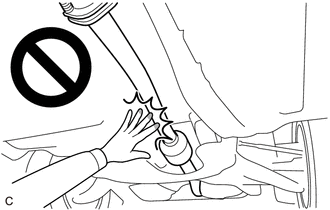
CAUTION:
-
To prevent burns, do not touch the engine, exhaust manifold or other high temperature components while the engine is hot.
.png)
-
To prevent burns, do not touch the engine, exhaust pipe or other high temperature components while the engine is hot.
PROCEDURE
1. REMOVE FRONT FLOOR COVER LH
Click here .gif)
2. REMOVE FRONT FLOOR COVER RH
Click here
3. REMOVE BODY MOUNTING PLATE
Click here
4. REMOVE NO. 1 EXHAUST PIPE SUPPORT BRACKET (for Lower Side)
Click here
5. REMOVE EXHAUST PIPE ASSEMBLY FRONT (TWC: Rear Catalyst)
| (a) Disconnect the 2 heated oxygen sensor connectors. |
|
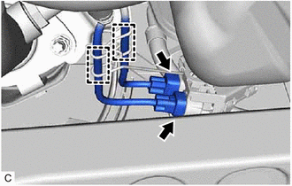
(b) Disengage the 2 wire harness clamps.
| (c) Remove the 4 bolts, 4 nuts and disconnect the front exhaust pipe assembly (TWC: Rear Catalyst). |
|
(d) Remove the front exhaust pipe assembly (TWC: Rear Catalyst) from the exhaust pipe support.
(e) Remove the 3 gaskets from the front exhaust pipe assembly (TWC: Rear Catalyst).
6. REMOVE AIR FUEL RATIO SENSOR (for Bank 1)
Click here
7. REMOVE NO. 1 EXHAUST MANIFOLD HEAT INSULATOR
| (a) Remove the 3 bolts and No. 1 exhaust manifold heat insulator from the exhaust manifold assembly RH (TWC: Front Catalyst). |
|
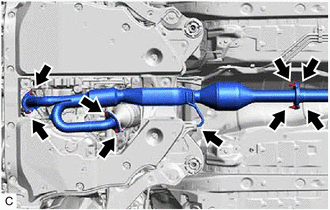
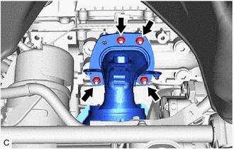
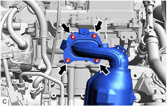
8. REMOVE EXHAUST MANIFOLD ASSEMBLY RH (TWC: Front Catalyst)
| (a) Using a 12 mm deep socket wrench, remove the 4 nuts and exhaust manifold assembly RH (TWC: Front Catalyst) from the cylinder head sub-assembly RH. |
|
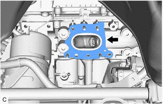
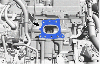
9. REMOVE EXHAUST MANIFOLD TO HEAD GASKET (for Bank 1)
| (a) Remove the exhaust manifold to head gasket (for Bank 1) from the cylinder head sub-assembly RH. |
|
10. REMOVE FRONT WHEEL OPENING EXTENSION PAD LH
Click here
11. REMOVE FRONT WHEEL OPENING EXTENSION PAD RH
Click here
12. REMOVE NO. 1 ENGINE UNDER COVER
Click here
13. REMOVE NO. 2 ENGINE UNDER COVER
Click here
14. REMOVE V-BANK COVER SUB-ASSEMBLY
Click here
15. REMOVE COOL AIR INTAKE DUCT SEAL
Click here
16. REMOVE AIR FUEL RATIO SENSOR (for Bank 2)
Click here
17. REMOVE ENGINE OIL LEVEL DIPSTICK GUIDE
Click here
18. REMOVE NO. 2 EXHAUST MANIFOLD HEAT INSULATOR
| (a) Remove the 3 bolts and No. 2 exhaust manifold heat insulator from the exhaust manifold assembly LH (TWC: Front Catalyst). |
|
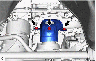
19. REMOVE NO. 2 MANIFOLD STAY
(a) Remove the bolt, nut and No. 2 manifold stay from the exhaust manifold assembly LH (TWC: Front Catalyst) and cylinder block sub-assembly.
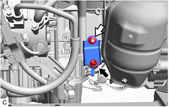
.png) | Bolt |
.png) | Nut |
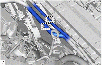
20. DISCONNECT NO. 5 WATER BY-PASS HOSE
| (a) Disengage the 2 clamps to disconnect the No. 5 water by-pass hose and No. 6 water by-pass hose from the hose clamp. |
|
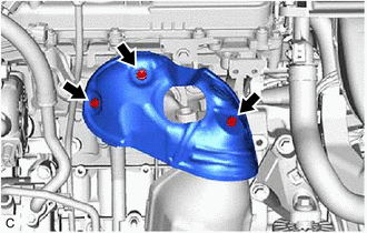
21. REMOVE EXHAUST MANIFOLD ASSEMBLY LH (TWC: Front Catalyst)
| (a) Using a 12 mm deep socket wrench, remove the 4 nuts and exhaust manifold assembly LH (TWC: Front Catalyst). |
|
22. REMOVE EXHAUST MANIFOLD TO HEAD GASKET (for Bank 2)
| (a) Remove the exhaust manifold to head gasket (for Bank 2) from the cylinder head sub-assembly. |
|
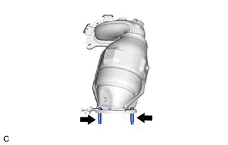
23. REMOVE STUD BOLT
HINT:
If a stud bolt is deformed or its threads are damaged, replace it.
| (a) Using an E8 "TORX" socket wrench, remove the 2 stud bolts from the exhaust manifold assembly LH (TWC: Front Catalyst). |
|
READ NEXT:
 Installation
INSTALLATION PROCEDURE 1. INSTALL STUD BOLT HINT: If a stud bolt is deformed or its threads are damaged, replace it. (a) Using an E8 "TORX" socket wrench, install the 2 stud bolts to the exhaust ma
Components
COMPONENTS ILLUSTRATION *A Type A *B Type B *1 FRONT FLOOR COVER RH - - N*m (kgf*cm, ft.*lbf): Specified torque - - ILLUSTRATION *A Type A *B Type B *1
SEE MORE:
Excessive Brake Pedal Travel (No Fluid Leaks and No Air in System)
CAUTION / NOTICE / HINT NOTICE: After replacing the skid control ECU (brake actuator assembly), perform acceleration sensor zero point calibration and store system information memorization. Click here PROCEDURE 1. PRE-INSPECTION (a) Brake pedal inspection (1) Perform a visual inspection a
Installation
INSTALLATION PROCEDURE 1. INSTALL MASS AIR FLOW METER SUB-ASSEMBLY HINT: Perform "Inspection After Repair" after replacing the mass air flow meter sub-assembly. Click here (a) Install the mass air flow meter sub-assembly to the air cleaner cap sub-assembly with the 2 screws. NOTICE:
If the m
