Lexus ES: Components
COMPONENTS
ILLUSTRATION
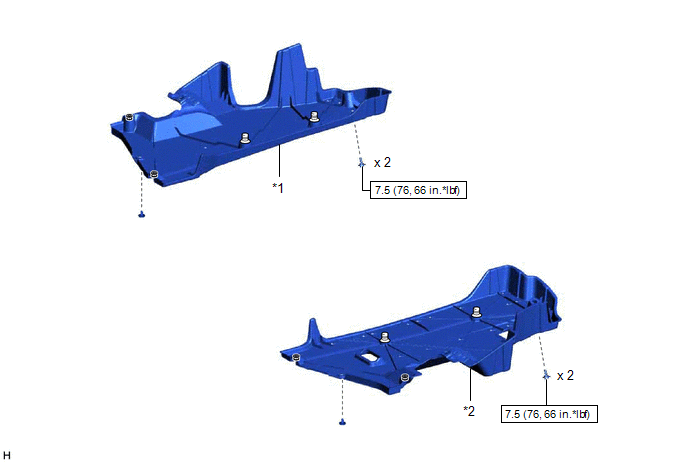
| *1 | NO. 1 FLOOR UNDER COVER | *2 | NO. 2 FLOOR UNDER COVER |
.png) | N*m (kgf*cm, ft.*lbf): Specified torque | - | - |
ILLUSTRATION
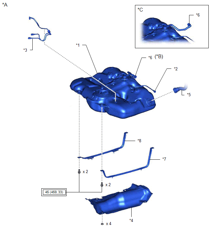
| *A | for TMC Made | *B | w/ Fuel Outlet Valve Assembly |
| *C | w/o Fuel Outlet Valve Assembly | - | - |
| *1 | FUEL TANK ASSEMBLY | *2 | FUEL TANK BREATHER TUBE SUB-ASSEMBLY |
| *3 | FUEL TANK MAIN TUBE SUB-ASSEMBLY | *4 | NO. 1 FUEL TANK PROTECTOR |
| *5 | FUEL TANK TO FILLER PIPE HOSE | *6 | FUEL CUT OFF VALVE WITH TUBE ASSEMBLY |
| *7 | NO. 1 FUEL TANK BAND SUB-ASSEMBLY LH | *8 | NO. 1 FUEL TANK BAND SUB-ASSEMBLY RH |
.png) | Tightening torque for "Major areas involving basic vehicle performance such as moving/turning/stopping": N*m (kgf*cm, ft.*lbf) | - | - |
ILLUSTRATION
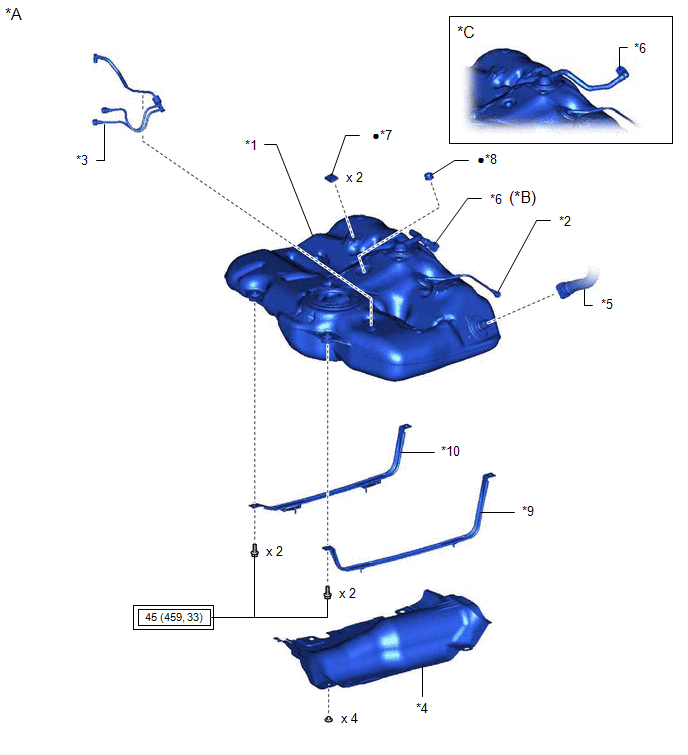
| *A | for TMMK Made | *B | w/ Fuel Outlet Valve Assembly |
| *C | w/o Fuel Outlet Valve Assembly | - | - |
| *1 | FUEL TANK ASSEMBLY | *2 | FUEL TANK BREATHER TUBE SUB-ASSEMBLY |
| *3 | FUEL TANK MAIN TUBE SUB-ASSEMBLY | *4 | NO. 1 FUEL TANK PROTECTOR |
| *5 | FUEL TANK TO FILLER PIPE HOSE | *6 | FUEL CUT OFF VALVE WITH TUBE ASSEMBLY |
| *7 | NO. 1 FUEL TANK CUSHION | *8 | NO. 2 FUEL TANK CUSHION |
| *9 | NO. 1 FUEL TANK BAND SUB-ASSEMBLY LH | *10 | NO. 1 FUEL TANK BAND SUB-ASSEMBLY RH |
| | Tightening torque for "Major areas involving basic vehicle performance such as moving/turning/stopping": N*m (kgf*cm, ft.*lbf) | ● | Non-reusable part |
READ NEXT:
 Removal
REMOVAL CAUTION / NOTICE / HINT The necessary procedures (adjustment, calibration, initialization or registration) that must be performed after parts are removed and installed, or replaced during fuel
Installation
INSTALLATION PROCEDURE 1. INSTALL NO. 1 FUEL TANK CUSHION (for TMMK Made) (a) Install 2 new No. 1 fuel tank cushions to the fuel tank assembly. 2. INSTALL NO. 2 FUEL TANK CUSHION (for TMMK Made) (a) I
SEE MORE:
Removal
REMOVAL CAUTION / NOTICE / HINT The necessary procedures (adjustment, calibration, initialization or registration) that must be performed after parts are removed and installed, or replaced during service plug grip removal/installation are shown below. Necessary Procedures After Parts Removed/Install
Camshaft Position "B" - Actuator Bank 1 Circuit Open (P001313,P002313)
DESCRIPTION The Variable Valve Timing (VVT) system adjusts the exhaust valve timing to improve driveability. The engine oil pressure turns the VVT controller to adjust the valve timing. The cam timing oil control solenoid assembly operates according to signals received from the ECM to control the po
