Lexus ES: Components
COMPONENTS
ILLUSTRATION
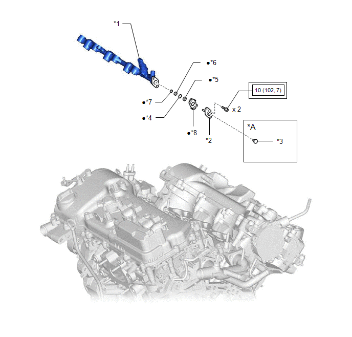
| *A | w/ Dust Cap | - | - |
| *1 | FUEL PRESSURE SENSOR (FUEL DELIVERY PIPE WITH SENSOR ASSEMBLY LH) | *2 | FUEL PIPE PLUG SUB-ASSEMBLY |
| *3 | DUST CAP SUB-ASSEMBLY | *4 | O-RING |
| *5 | NO. 1 FUEL INJECTOR BACK-UP RING | *6 | NO. 2 FUEL INJECTOR BACK-UP RING |
| *7 | NO. 3 FUEL INJECTOR BACK-UP RING | *8 | GASKET |
.png) | Tightening torque for "Major areas involving basic vehicle performance such as moving/turning/stopping": N*m (kgf*cm, ft.*lbf) | ● | Non-reusable part |
READ NEXT:
 Removal
REMOVAL CAUTION / NOTICE / HINT The necessary procedures (adjustment, calibration, initialization or registration) that must be performed after parts are removed and installed, or replaced during fuel
Inspection
INSPECTION PROCEDURE 1. INSPECT FUEL PRESSURE SENSOR (FUEL DELIVERY PIPE WITH SENSOR ASSEMBLY LH) NOTICE:
Do not remove the fuel pressure sensor from the fuel delivery pipe with sensor assembly LH.
Installation
INSTALLATION PROCEDURE 1. INSTALL FUEL PIPE PLUG SUB-ASSEMBLY (a) Install a new O-ring, No. 1 fuel injector back-up ring, No. 2 fuel injector back-up ring and No. 3 fuel injector back-up ring to the f
SEE MORE:
ECU Malfunction (B1370)
DESCRIPTION This DTC is stored when the windshield wiper motor assembly detects an internal malfunction. DTC No. Detection Item DTC Detection Condition Trouble Area Memory DTC Output from B1370 ECU Malfunction
Battery voltage is 9.5 V or more
A malfunction is detected f
On-vehicle Inspection
ON-VEHICLE INSPECTION CAUTION / NOTICE / HINT CAUTION: To prevent injury due to contact with an operating V-ribbed belt or cooling fan, keep your hands and clothing away from the V-ribbed belt and cooling fan when working in the engine compartment with the engine running or the ignition switch ON.
© 2016-2026 Copyright www.lexguide.net
