Lexus ES: Components
COMPONENTS
ILLUSTRATION
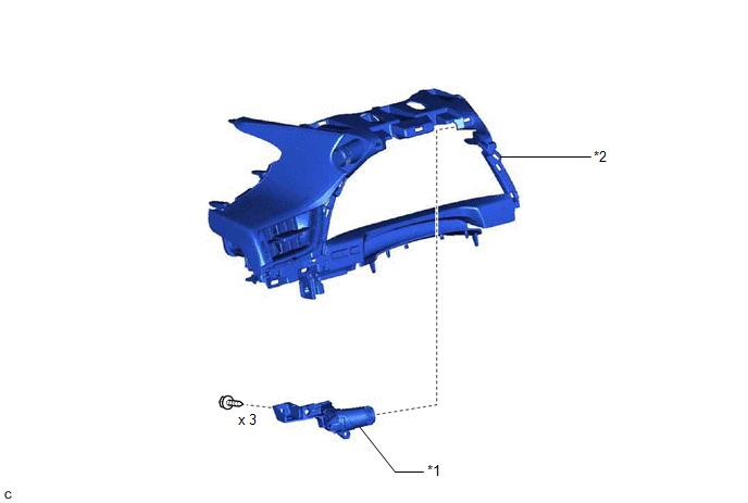
| *1 | DRIVE MODE SELECT SWITCH (COMBINATION SWITCH ASSEMBLY) | *2 | INSTRUMENT CLUSTER FINISH PANEL ASSEMBLY |
READ NEXT:
 Inspection
INSPECTION PROCEDURE 1. INSPECT DRIVE MODE SELECT SWITCH (COMBINATION SWITCH ASSEMBLY) (a) Inspect the "Normal" mode switch: (1) Measure the resistance according to the value(s) in the table below.
Installation
INSTALLATION PROCEDURE 1. INSTALL DRIVE MODE SELECT SWITCH (COMBINATION SWITCH ASSEMBLY) (a) Install the drive mode select switch (combination switch assembly) to the instrument cluster finish panel a
Removal
REMOVAL PROCEDURE 1. REMOVE INSTRUMENT CLUSTER FINISH PANEL ASSEMBLY Click here 2. REMOVE DRIVE MODE SELECT SWITCH (COMBINATION SWITCH ASSEMBLY) (a) Disconnect the drive mode select switch (comb
SEE MORE:
Components
COMPONENTS ILLUSTRATION *1 REAR DOOR FRONT WINDOW FRAME MOULDING *2 REAR DOOR WEATHERSTRIP *3 REAR DOOR WINDOW FRAME MOULDING SUB-ASSEMBLY *4 RIVET ● Non-reusable part - -
DC/DC Converter Current Sensor Signal Stuck In Range (P0E512A)
DTC SUMMARY MALFUNCTION DESCRIPTION This DTC is stored if the value of the reactor current sensor does not change. The cause of this malfunction may be one of the following: Area Main Malfunction Description Inverter
Inverter internal circuit malfunction
Malfunction in ECU that contr
© 2016-2026 Copyright www.lexguide.net
