Lexus ES: Components
COMPONENTS
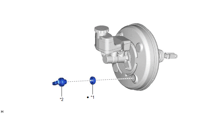
ILLUSTRATION

| *1 | CHECK VALVE GROMMET | *2 | VACUUM WARNING SWITCH ASSEMBLY |
| ● | Non-reusable part | - | - |
READ NEXT:
 Installation
INSTALLATION PROCEDURE 1. INSTALL CHECK VALVE GROMMET (a) Install a new check valve grommet to the brake booster assembly. 2. INSTALL VACUUM WARNING SWITCH ASSEMBLY (a) Install the vacuum warning swit
 Installation
INSTALLATION PROCEDURE 1. INSTALL CHECK VALVE GROMMET (a) Install a new check valve grommet to the brake booster assembly. 2. INSTALL VACUUM WARNING SWITCH ASSEMBLY (a) Install the vacuum warning swit
 On-vehicle Inspection
ON-VEHICLE INSPECTION PROCEDURE 1. INSPECT BRAKE FLUID LEVEL IN RESERVOIR Click here 2. INSPECT BRAKE BOOSTER ASSEMBLY Click here 3. INSPECT VACUUM WARNING SWITCH ASSEMBLY (a) Start the engine and
SEE MORE:
 On-vehicle Inspection
ON-VEHICLE INSPECTION CAUTION / NOTICE / HINT CAUTION:
To prevent burns, do not touch the engine, exhaust manifold or other high temperature components while the engine is hot.
To prevent burns, do not remove the oil pressure and temperature sensor while the engine is hot. PROCEDURE 1. INS
 HVAC Control Module to Hybrid Powertrain Control Module Invalid Serial Data Received (U042481)
DESCRIPTION If the hybrid vehicle control ECU receives an invalid compressor control request from the air conditioning amplifier assembly via CAN communication, it will store this DTC. DTC No. Detection Item DTC Detection Condition Trouble Area MIL Warning Indicate U042481 HVAC Co
© 2016-2026 Copyright www.lexguide.net

