Lexus ES: Emergency Call Switch Illumination Circuit
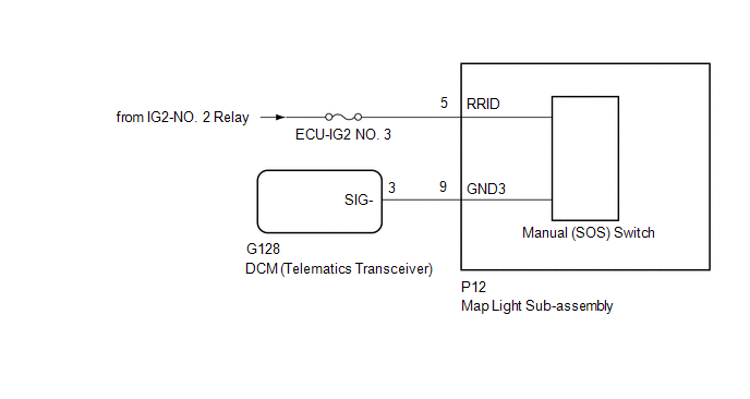
WIRING DIAGRAM
CAUTION / NOTICE / HINT
NOTICE:
-
Depending on the parts that are replaced during vehicle inspection or maintenance, performing initialization, registration or calibration may be needed. Refer to Precaution for Safety Connect System.
Click here
.gif)
- Inspect the fuses for circuits related to this system before performing the following procedure.
PROCEDURE
| 1. | CHECK HARNESS AND CONNECTOR (MAP LIGHT SUB-ASSEMBLY (MANUAL (SOS) SWITCH) POWER SOURCE) |
(a) Disconnect the G128 DCM (telematics transceiver) connector.
(b) Disconnect the P12 map light sub-assembly (manual (SOS) switch) connector.
(c) Measure the voltage according to the value(s) in the table below.
Standard Voltage:
| Tester Connection | Switch Condition | Specified Condition |
|---|---|---|
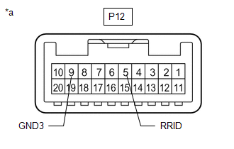
| P12-5 (RRID) - Body Ground | Power switch on (IG) | 11 to 14 V |
(d) Measure the resistance according to the value(s) in the table below.
Standard Resistance:
| Tester Connection | Condition | Specified Condition |
|---|---|---|
| G128-3 (SIG-) - P12-9 (GND3) | Always | Below 1 Ω |
| G128-3 (SIG-) or P12-9 (GND3) - Body ground | Always | 10 kΩ or higher |
| NG | .gif) | REPAIR OR REPLACE HARNESS OR CONNECTOR |
|
.gif)
| 2. | INSPECT MAP LIGHT SUB-ASSEMBLY (MANUAL (SOS) SWITCH) |
| (a) Remove the map light sub-assembly (manual (SOS) switch). Click here |
|
(b) Apply auxiliary battery voltage to the connector and check that the manual (SOS) switch illumination comes on.
OK:
| Measurement Condition | Condition | Specified Condition |
|---|---|---|
| Auxiliary battery positive (+) → P12-5 (RRID) Auxiliary battery negative (-) → P12-9 (GND3) | Always | Manual (SOS) switch illumination cones on |
| NG | | REPLACE MAP LIGHT SUB-ASSEMBLY (MANUAL (SOS) SWITCH) |
|
| 3. | REPLACE DCM (TELEMATICS TRANSCEIVER) |
(a) Replace the DCM (telematics transceiver) with a new one.
Click here
NOTICE:
- The power switch must be off.
- Do not exchange the DCM (telematics transceiver) with one from another vehicle.
| NEXT | | PERFORM DCM ACTIVATION |
READ NEXT:
 Green Indicator Remains Off
DESCRIPTION After power switch on (IG), the DCM (telematics transceiver) will enter into self check mode. The manual (SOS) switch red indicator will illuminate for 2 seconds and turn off followed by t
How To Proceed With Troubleshooting
CAUTION / NOTICE / HINT HINT:
Use the following procedure to troubleshoot the safety connect system.
*: Use the Techstream.
PROCEDURE 1. VEHICLE BROUGHT TO WORKSHOP
NEXT
Initialization
INITIALIZATION RESET BACK-UP BATTERY CONDITION HINT: If the back-up battery (mobilephone battery) has been replaced, it is necessary to perform the Reset Backup Battery Condition procedure. (a) Connec
SEE MORE:
Data List / Active Test
DATA LIST / ACTIVE TEST ACTIVE TEST HINT: Using the Techstream to perform Active Tests allows relays, VSVs, actuators and other items to be operated without removing any parts. This non-intrusive functional inspection can be very useful because intermittent operation may be discovered before parts o
Components
COMPONENTS ILLUSTRATION *1 ENGINE ASSEMBLY WITH TRANSAXLE *2 FRONT BUMPER EXTENSION SUB-ASSEMBLY RH *3 FRONT BUMPER EXTENSION SUB-ASSEMBLY LH *4 FRONT SUSPENSION MEMBER BRACKET SUB-ASSEMBLY RH *5 FRONT SUSPENSION MEMBER BRACKET SUB-ASSEMBLY LH *6 NO. 2 ENGINE MOUNTING S
