Lexus ES: Check Bus 4 Line for Short to GND
DESCRIPTION
There may be a short circuit between one of the CAN bus lines and GND when there is no resistance between terminal 22 (CA2H) of the central gateway ECU (network gateway ECU) and terminal 4 (CG) of the DLC3, or terminal 7 (CA2L) of the central gateway ECU (network gateway ECU) and terminal 4 (CG) of the DLC3.
| Symptom | Trouble Area |
|---|---|
| There is no resistance between terminal 22 (CA2H) of the central gateway ECU (network gateway ECU) and terminal 4 (CG) of the DLC3, or terminal 7 (CA2L) of the central gateway ECU (network gateway ECU) and terminal 4 (CG) of the DLC3. |
|
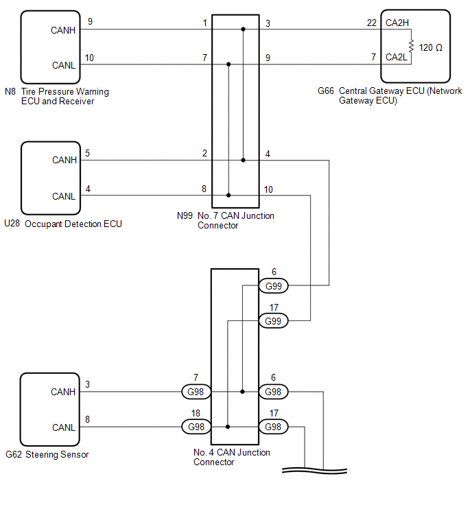
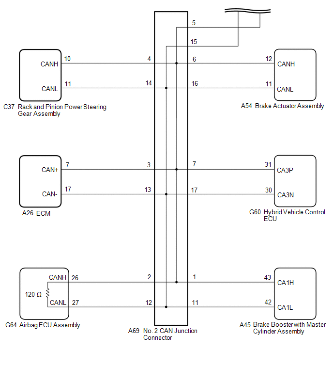
WIRING DIAGRAM
CAUTION / NOTICE / HINT
CAUTION:
When performing the confirmation driving pattern, obey all speed limits and traffic laws.
NOTICE:
-
Because the order of diagnosis is important to allow correct diagnosis, make sure to begin troubleshooting using How to Proceed with Troubleshooting when CAN communication system related DTCs are output.
Click here
.gif)
- Before measuring the resistance of the CAN bus, turn the power switch off and leave the vehicle for 1 minute or more without operating the key or any switches, or opening or closing the doors. After that, disconnect the cable from the negative (-) auxiliary battery terminal and leave the vehicle for 1 minute or more before measuring the resistance.
-
After turning the power switch off, waiting time may be required before disconnecting the cable from the negative (-) auxiliary battery terminal. Therefore, make sure to read the disconnecting the cable from the negative (-) auxiliary battery terminal notices before proceeding with work.
Click here
-
After performing repairs, perform the DTC check procedure and confirm that the DTCs are not output again.
DTC check procedure: Turn the power switch on (IG) and wait for 1 minute or more. Then operate the suspected malfunctioning system and drive the vehicle at 60 km/h (37 mph) or more for 5 minutes or more.
-
After the repair, perform the CAN bus check and check that all the ECUs and sensors connected to the CAN communication system are displayed as normal.
Click here
-
Before replacing the hybrid vehicle control ECU, refer to Registration.
Click here
HINT:
- Before disconnecting related connectors for inspection, push in on each connector body to check that the connector is not loose or disconnected.
- When a connector is disconnected, check that the terminals and connector body are not cracked, deformed or corroded.
PROCEDURE
| 1. | CHECK FOR SHORT TO GND IN CAN BUS LINE (NO. 7 CAN JUNCTION CONNECTOR) |
(a) Disconnect the cable from the negative (-) auxiliary battery terminal.
(b) Disconnect the N99 No. 7 CAN junction connector.
(c) Measure the resistance according to the value(s) in the table below.
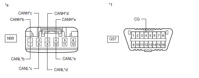
| *1 | DLC3 | - | - |
| *a | Front view of wire harness connector (to No. 7 CAN Junction Connector) | *b | to Tire Pressure Warning ECU and Receiver |
| *c | to Occupant Detection ECU | *d | to Central Gateway ECU (Network Gateway ECU) |
| *e | to No. 4 CAN Junction Connector | - | - |
Standard Resistance:
| Tester Connection | Condition | Specified Condition | Connected to |
|---|---|---|---|
| N99-1 (CANH) - G57-4 (CG) | Cable disconnected from negative (-) auxiliary battery terminal | 200 Ω or higher | Tire pressure warning ECU and receiver |
| N99-7 (CANL) - G57-4 (CG) | |||
| N99-2 (CANH) - G57-4 (CG) | Cable disconnected from negative (-) auxiliary battery terminal | 200 Ω or higher | Occupant detection ECU |
| N99-8 (CANL) - G57-4 (CG) | |||
| N99-3 (CANH) - G57-4 (CG) | Cable disconnected from negative (-) auxiliary battery terminal | 200 Ω or higher | Central gateway ECU (network gateway ECU) |
| N99-9 (CANL) - G57-4 (CG) | |||
| N99-4 (CANH) - G57-4 (CG) | Cable disconnected from negative (-) auxiliary battery terminal | 200 Ω or higher | No. 4 CAN junction connector |
| N99-10 (CANL) - G57-4 (CG) |
| Result | Proceed to |
|---|---|
| OK | A |
| NG (Line to central gateway ECU (network gateway ECU)) | B |
| NG (Line to No. 4 CAN junction connector) | C |
| NG (Line to ECU or sensor) | D |
| A | .gif) | REPLACE NO. 7 CAN JUNCTION CONNECTOR |
| C | | GO TO STEP 3 |
| D | | GO TO STEP 6 |
|
.gif)
| 2. | CHECK FOR SHORT TO GND IN CAN BUS LINE (NO. 7 CAN JUNCTION CONNECTOR - CENTRAL GATEWAY ECU (NETWORK GATEWAY ECU)) |
(a) Disconnect the G66 central gateway ECU (network gateway ECU) connector.
(b) Measure the resistance according to the value(s) in the table below.
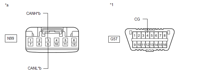
| *1 | DLC3 | - | - |
| *a | Front view of wire harness connector (to No. 7 CAN Junction Connector) | *b | to Central Gateway ECU (Network Gateway ECU) |
Standard Resistance:
| Tester Connection | Condition | Specified Condition |
|---|---|---|
| N99-3 (CANH) - G57-4 (CG) | Cable disconnected from negative (-) auxiliary battery terminal | 200 Ω or higher |
| N99-9 (CANL) - G57-4 (CG) |
| OK | | REPLACE CENTRAL GATEWAY ECU (NETWORK GATEWAY ECU) |
| NG | | REPAIR OR REPLACE CAN MAIN BUS LINE OR CONNECTOR (NO. 7 CAN JUNCTION CONNECTOR - CENTRAL GATEWAY ECU (NETWORK GATEWAY ECU)) |
| 3. | CHECK FOR SHORT TO GND IN CAN BUS LINE (NO. 4 CAN JUNCTION CONNECTOR - NO. 7 CAN JUNCTION CONNECTOR) |
(a) Disconnect the G99 No. 4 CAN junction connector.
(b) Measure the resistance according to the value(s) in the table below.
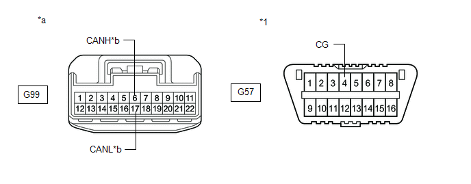
| *1 | DLC3 | - | - |
| *a | Front view of wire harness connector (to No. 4 CAN Junction Connector) | *b | to No. 7 CAN Junction Connector |
Standard Resistance:
| Tester Connection | Condition | Specified Condition |
|---|---|---|
| G99-6 (CANH) - G57-4 (CG) | Cable disconnected from negative (-) auxiliary battery terminal | 200 Ω or higher |
| G99-17 (CANL) - G57-4 (CG) |
| NG | | REPAIR OR REPLACE CAN MAIN BUS LINE OR CONNECTOR (NO. 4 CAN JUNCTION CONNECTOR - NO. 7 CAN JUNCTION CONNECTOR) |
|
| 4. | CHECK FOR SHORT TO GND IN CAN BUS LINE (NO. 4 CAN JUNCTION CONNECTOR) |
(a) Disconnect the G98 No. 4 CAN junction connector.
(b) Measure the resistance according to the value(s) in the table below.
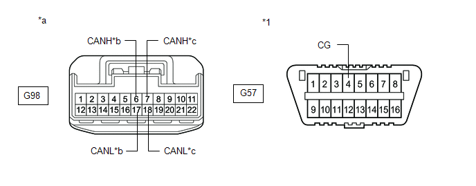
| *1 | DLC3 | - | - |
| *a | Front view of wire harness connector (to No. 4 CAN Junction Connector) | *b | to No. 2 CAN Junction Connector |
| *c | to Steering Sensor | - | - |
Standard Resistance:
| Tester Connection | Condition | Specified Condition | Connected to |
|---|---|---|---|
| G98-6 (CANH) - G57-4 (CG) | Cable disconnected from negative (-) auxiliary battery terminal | 200 Ω or higher | No. 2 CAN junction connector |
| G98-17 (CANL) - G57-4 (CG) | |||
| G98-7 (CANH) - G57-4 (CG) | Cable disconnected from negative (-) auxiliary battery terminal | 200 Ω or higher | Steering sensor |
| G98-18 (CANL) - G57-4 (CG) |
| Result | Proceed to |
|---|---|
| OK | A |
| NG (Line to No. 2 CAN junction connector) | B |
| NG (Line to ECU or sensor) | C |
| A | | REPLACE NO. 4 CAN JUNCTION CONNECTOR |
| C | | GO TO STEP 6 |
|
| 5. | CHECK FOR SHORT TO GND IN CAN BUS LINE (NO. 2 CAN JUNCTION CONNECTOR) |
(a) Disconnect the A69 No. 2 CAN junction connector.
(b) Measure the resistance according to the value(s) in the table below.
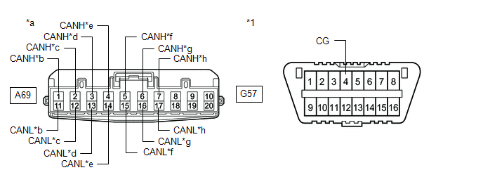
| *1 | DLC3 | - | - |
| *a | Front view of wire harness connector (to No. 2 CAN Junction Connector) | *b | to Brake Booster with Master Cylinder Assembly |
| *c | to Airbag ECU Assembly | *d | to ECM |
| *e | to Rack and Pinion Power Steering Gear Assembly | *f | to No. 4 CAN Junction Connector |
| *g | to Brake Actuator Assembly | *h | to Hybrid Vehicle Control ECU |
Standard Resistance:
| Tester Connection | Condition | Specified Condition | Connected to |
|---|---|---|---|
| A69-1 (CANH) - G57-4 (CG) | Cable disconnected from negative (-) auxiliary battery terminal | 200 Ω or higher | Brake booster with master cylinder assembly |
| A69-11 (CANL) - G57-4 (CG) | |||
| A69-2 (CANH) - G57-4 (CG) | Cable disconnected from negative (-) auxiliary battery terminal | 200 Ω or higher | Airbag ECU assembly |
| A69-12 (CANL) - G57-4 (CG) | |||
| A69-3 (CANH) - G57-4 (CG) | Cable disconnected from negative (-) auxiliary battery terminal | 200 Ω or higher | ECM |
| A69-13 (CANL) - G57-4 (CG) | |||
| A69-4 (CANH) - G57-4 (CG) | Cable disconnected from negative (-) auxiliary battery terminal | 200 Ω or higher | Rack and pinion power steering gear assembly |
| A69-14 (CANL) - G57-4 (CG) | |||
| A69-5 (CANH) - G57-4 (CG) | Cable disconnected from negative (-) auxiliary battery terminal | 200 Ω or higher | No. 4 CAN junction connector |
| A69-15 (CANL) - G57-4 (CG) | |||
| A69-6 (CANH) - G57-4 (CG) | Cable disconnected from negative (-) auxiliary battery terminal | 200 Ω or higher | Brake actuator assembly |
| A69-16 (CANL) - G57-4 (CG) | |||
| A69-7 (CANH) - G57-4 (CG) | Cable disconnected from negative (-) auxiliary battery terminal | 200 Ω or higher | Hybrid vehicle control ECU |
| A69-17 (CANL) - G57-4 (CG) |
| Result | Proceed to |
|---|---|
| OK | A |
| NG (Line to No. 4 CAN junction connector) | B |
| NG (Line to ECU or sensor) | C |
| A | | REPLACE NO. 2 CAN JUNCTION CONNECTOR |
| B | | REPAIR OR REPLACE CAN MAIN BUS LINE OR CONNECTOR (NO. 2 CAN JUNCTION CONNECTOR - NO. 4 CAN JUNCTION CONNECTOR) |
| C | | GO TO STEP 6 |
| 6. | CHECK FOR SHORT TO GND IN CAN BUS LINE (ECU OR SENSOR) |
(a) Reconnect all wire harness connectors.
(b) Disconnect the connector that includes terminals CANH and CANL from the ECU or sensor to which the bus line shorted to GND is connected.
Click here
(c) Measure the resistance according to the value(s) in the table below.
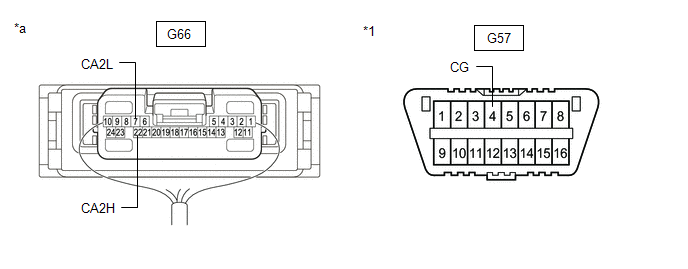
| *1 | DLC3 | - | - |
| *a | Component with harness connected (Central Gateway ECU (Network Gateway ECU)) | - | - |
Standard Resistance:
| Tester Connection | Condition | Specified Condition |
|---|---|---|
| G66-22 (CA2H) - G57-4 (CG) | Cable disconnected from negative (-) auxiliary battery terminal | 200 Ω or higher |
| G66-7 (CA2L) - G57-4 (CG) |
HINT:
- If the resistance changes to 200 Ω or higher when the connector is disconnected from the ECU or sensor, there may be a short in the ECU or sensor.
- If the resistance does not become normal when the connector is disconnected from the ECU or sensor, check for a short to ground in the wire harness and repair or replace the wire harness or connector if necessary.
| OK | | REPLACE ECU OR SENSOR |
| NG | | REPAIR OR REPLACE HARNESS OR CONNECTOR |
READ NEXT:
 Check Bus 4 Line for Short to +B
DESCRIPTION There may be a short circuit between one of the CAN bus lines and +B when there is no resistance between terminal 22 (CA2H) of the central gateway ECU (network gateway ECU) and terminal 16
Check Bus 4 Lines for Short Circuit
DESCRIPTION There may be a short circuit between the CAN main bus lines and/or CAN branch lines when the resistance between terminals 22 (CA2H) and 7 (CA2L) of the central gateway ECU (network gateway
Open in Bus 4 Main Bus Line
DESCRIPTION There may be an open circuit in one of the CAN main bus lines when the resistance between terminals 22 (CA2H) and 7 (CA2L) of the central gateway ECU (network gateway ECU) is 70 Ω or high
SEE MORE:
Reassembly
REASSEMBLY CAUTION / NOTICE / HINT HINT:
Use the same procedure for the RH side and LH side.
The following procedure is for the LH side.
PROCEDURE 1. INSTALL HEADLIGHT SEAL (for TMC Made) HINT: Perform this procedure only when replacement of the headlight seal is necessary. (a) Clean the ins
Dynamic radar cruise control with
full-speed range
In vehicle-to-vehicle distance control
mode, the vehicle automatically
accelerates, decelerates and
stops to match the speed changes
of the preceding vehicle even if the
accelerator pedal is not depressed.
In constant speed control mode,
the vehicle runs at a fixed speed.
Use the dynamic
