Lexus ES: Check Bus 3 Line for Short to GND
DESCRIPTION
There may be a short circuit between one of the CAN bus lines and GND when there is no resistance between terminal 6 (CA3H) of the central gateway ECU (network gateway ECU) and terminal 4 (CG) of the DLC3, or terminal 21 (CA3L) of the central gateway ECU (network gateway ECU) and terminal 4 (CG) of the DLC3.
| Symptom | Trouble Area |
|---|---|
| There is no resistance between terminal 6 (CA3H) of the central gateway ECU (network gateway ECU) and terminal 4 (CG) of the DLC3, or terminal 21 (CA3L) of the central gateway ECU (network gateway ECU) and terminal 4 (CG) of the DLC3. |
|
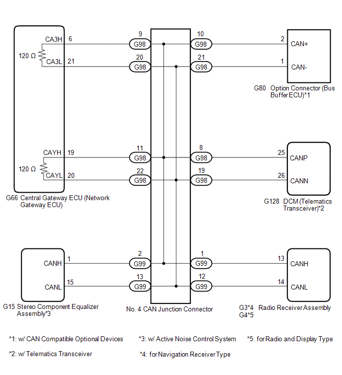
WIRING DIAGRAM
CAUTION / NOTICE / HINT
CAUTION:
When performing the confirmation driving pattern, obey all speed limits and traffic laws.
NOTICE:
-
Because the order of diagnosis is important to allow correct diagnosis, make sure to begin troubleshooting using How to Proceed with Troubleshooting when CAN communication system related DTCs are output.
Click here
.gif)
- Before measuring the resistance of the CAN bus, turn the engine switch off and leave the vehicle for 1 minute or more without operating the key or any switches, or opening or closing the doors. After that, disconnect the cable from the negative (-) battery terminal and leave the vehicle for 1 minute or more before measuring the resistance.
-
After turning the engine switch off, waiting time may be required before disconnecting the cable from the negative (-) battery terminal. Therefore, make sure to read the disconnecting the cable from the negative (-) battery terminal notices before proceeding with work.
Click here
-
After performing repairs, perform the DTC check procedure and confirm that the DTCs are not output again.
DTC check procedure: Turn the engine switch on (IG) and wait for 1 minute or more. Then operate the suspected malfunctioning system and drive the vehicle at 60 km/h (37 mph) or more for 5 minutes or more.
-
After the repair, perform the CAN bus check and check that all the ECUs and sensors connected to the CAN communication system are displayed as normal.
Click here
-
Before replacing the DCM (telematics transceiver), refer to Registration.
Click here
HINT:
- Before disconnecting related connectors for inspection, push in on each connector body to check that the connector is not loose or disconnected.
- When a connector is disconnected, check that the terminals and connector body are not cracked, deformed or corroded.
PROCEDURE
| 1. | CHECK FOR SHORT TO GND IN CAN BUS LINE (NO. 4 CAN JUNCTION CONNECTOR) |
(a) Disconnect the cable from the negative (-) battery terminal.
(b) Disconnect the G98 No. 4 CAN junction connector.
(c) Measure the resistance according to the value(s) in the table below.
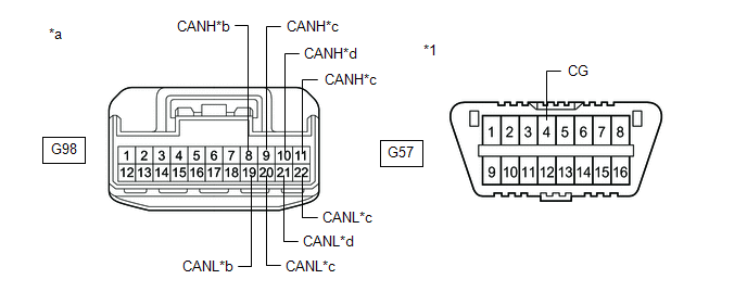
| *1 | DLC3 | - | - |
| *a | Front view of wire harness connector (to No. 4 CAN Junction Connector) | *b | to DCM (Telematics Transceiver) (w/ Telematics Transceiver) |
| *c | to Central Gateway ECU (Network Gateway ECU) | *d | to Option Connector (Bus Buffer ECU) (w/ CAN Compatible Optional Devices) |
Standard Resistance:
| Tester Connection | Condition | Specified Condition | Connected to |
|---|---|---|---|
| G98-8 (CANH) - G57-4 (CG) | Cable disconnected from negative (-) battery terminal | 200 Ω or higher | DCM (telematics transceiver)*1 |
| G98-19 (CANL) - G57-4 (CG) | |||
| G98-9 (CANH) - G57-4 (CG) | Cable disconnected from negative (-) battery terminal | 200 Ω or higher | Central gateway ECU (network gateway ECU) |
| G98-20 (CANL) - G57-4 (CG) | |||
| G98-10 (CANH) - G57-4 (CG) | Cable disconnected from negative (-) battery terminal | 200 Ω or higher | Option connector (bus buffer ECU)*2 |
| G98-21 (CANL) - G57-4 (CG) | |||
| G98-11 (CANH) - G57-4 (CG) | Cable disconnected from negative (-) battery terminal | 200 Ω or higher | Central gateway ECU (network gateway ECU) |
| G98-22 (CANL) - G57-4 (CG) |
- *1: w/ Telematics Transceiver
- *2: w/ CAN Compatible Optional Devices
HINT:
If there is a short to ground in a CAN bus line without any CAN compatible optional devices connected to the option connector, repair or replace the CAN bus branch line or the option connector.
| Result | Proceed to |
|---|---|
| OK | A |
| NG (Line to central gateway ECU (network gateway ECU)) | B |
| NG (Line to ECU or sensor) | C |
| B | .gif) | GO TO STEP 3 |
| C | | GO TO STEP 4 |
|
.gif)
| 2. | CHECK FOR SHORT TO GND IN CAN BUS LINE (NO. 4 CAN JUNCTION CONNECTOR) |
(a) Disconnect the G99 No. 4 CAN junction connector.
(b) Measure the resistance according to the value(s) in the table below.
.png)
| *1 | DLC3 | - | - |
| *a | Front view of wire harness connector (to No. 4 CAN Junction Connector) | *b | to Radio Receiver Assembly |
| *c | to Stereo Component Equalizer Assembly (w/ Active Noise Control System) | - | - |
Standard Resistance:
| Tester Connection | Condition | Specified Condition | Connected to |
|---|---|---|---|
| G99-1 (CANH) - G57-4 (CG) | Cable disconnected from negative (-) battery terminal | 200 Ω or higher | Radio receiver assembly |
| G99-12 (CANL) - G57-4 (CG) | |||
| G99-2 (CANH) - G57-4 (CG) | Cable disconnected from negative (-) battery terminal | 200 Ω or higher | Stereo component equalizer assembly* |
| G99-13 (CANL) - G57-4 (CG) |
- *: w/ Active Noise Control System
| OK | | REPLACE NO. 4 CAN JUNCTION CONNECTOR |
| NG | | GO TO STEP 4 |
| 3. | CHECK FOR SHORT TO GND IN CAN BUS LINE (NO. 4 CAN JUNCTION CONNECTOR - CENTRAL GATEWAY ECU (NETWORK GATEWAY ECU)) |
(a) Disconnect the G66 central gateway ECU (network gateway ECU) connector.
(b) Measure the resistance according to the value(s) in the table below.
.png)
| *1 | DLC3 | - | - |
| *a | Front view of wire harness connector (to No. 4 CAN Junction Connector) | *b | to Central Gateway ECU (Network Gateway ECU) |
Standard Resistance:
| Tester Connection | Condition | Specified Condition |
|---|---|---|
| G98-9 (CANH) - G57-4 (CG) | Cable disconnected from negative (-) battery terminal | 200 Ω or higher |
| G98-20 (CANL) - G57-4 (CG) | ||
| G98-11 (CANH) - G57-4 (CG) | Cable disconnected from negative (-) battery terminal | 200 Ω or higher |
| G98-22 (CANL) - G57-4 (CG) |
| OK | | REPLACE CENTRAL GATEWAY ECU (NETWORK GATEWAY ECU) |
| NG | | REPAIR OR REPLACE CAN MAIN BUS LINE OR CONNECTOR (NO. 4 CAN JUNCTION CONNECTOR - CENTRAL GATEWAY ECU (NETWORK GATEWAY ECU)) |
| 4. | CHECK FOR SHORT TO GND IN CAN BUS LINE (ECU OR SENSOR) |
(a) Reconnect all wire harness connectors.
(b) Disconnect the connector that includes terminals CANH and CANL from the ECU or sensor to which the bus line shorted to GND is connected.
Click here
(c) Measure the resistance according to the value(s) in the table below.
.png)
| *1 | DLC3 | - | - |
| *a | Component with harness connected (Central Gateway ECU (Network Gateway ECU)) | - | - |
Standard Resistance:
| Tester Connection | Condition | Specified Condition |
|---|---|---|
| G66-6 (CA3H) - G57-4 (CG) | Cable disconnected from negative (-) battery terminal | 200 Ω or higher |
| G66-21 (CA3L) - G57-4 (CG) |
HINT:
- If the resistance changes to 200 Ω or higher when the connector is disconnected from the ECU or sensor, there may be a short in the ECU or sensor.
- If the resistance does not become normal when the connector is disconnected from the ECU or sensor, check for a short to ground in the wire harness and repair or replace the wire harness or connector if necessary.
| OK | | REPLACE ECU OR SENSOR |
| NG | | REPAIR OR REPLACE HARNESS OR CONNECTOR |
READ NEXT:
 Check Bus 3 Line for Short to +B
DESCRIPTION There may be a short circuit between one of the CAN bus lines and +B when there is no resistance between terminal 6 (CA3H) of the central gateway ECU (network gateway ECU) and terminal 16
Check Bus 3 Line for Short to +B
DESCRIPTION There may be a short circuit between one of the CAN bus lines and +B when there is no resistance between terminal 6 (CA3H) of the central gateway ECU (network gateway ECU) and terminal 16
Check Bus 3 Lines for Short Circuit
DESCRIPTION There may be a short circuit between the CAN main bus lines and/or CAN branch lines when the resistance between terminals 6 (CA3H) and 21 (CA3L) of the central gateway ECU (network gateway
SEE MORE:
Tilt and Telescopic Manual Switch Circuit Circuit Voltage Out of Range (B26031C)
DESCRIPTION Different voltage values are sent to the multiplex tilt and telescopic ECU by operating the tilt and telescopic switch. The multiplex tilt and telescopic ECU then judges which motor and in which direction that motor should operate based on the voltage value. DTC No. Detection Item
Components
COMPONENTS ILLUSTRATION *1 NO. 1 FLOOR UNDER COVER *2 NO. 2 FLOOR UNDER COVER N*m (kgf*cm, ft.*lbf): Specified torque - - ILLUSTRATION *1 NO. 2 FUEL TANK PROTECTOR *2 NO. 1 FUEL TANK PROTECTOR SUB-ASSEMBLY *3 FUEL TANK MAIN TUBE SUB-ASSEMBLY *4 INLET FUEL
