Lexus ES: Check Bus 2 Lines for Short Circuit
DESCRIPTION
There may be a short circuit between the CAN main bus lines and/or CAN branch lines when the resistance between terminals 18 (CA4H) and 17 (CA4L) of the central gateway ECU (network gateway ECU) is below 54 Ω.
| Symptom | Trouble Area |
|---|---|
| Resistance between terminals 18 (CA4H) and 17 (CA4L) of the central gateway ECU (network gateway ECU) is below 54 Ω. |
|
WIRING DIAGRAM
.png)
.png)
CAUTION / NOTICE / HINT
CAUTION:
When performing the confirmation driving pattern, obey all speed limits and traffic laws.
NOTICE:
-
Because the order of diagnosis is important to allow correct diagnosis, make sure to begin troubleshooting using How to Proceed with Troubleshooting when CAN communication system related DTCs are output.
Click here
.gif)
- Before measuring the resistance of the CAN bus, turn the power switch off and leave the vehicle for 1 minute or more without operating the key or any switches, or opening or closing the doors. After that, disconnect the cable from the negative (-) auxiliary battery terminal and leave the vehicle for 1 minute or more before measuring the resistance.
-
After turning the power switch off, waiting time may be required before disconnecting the cable from the negative (-) auxiliary battery terminal. Therefore, make sure to read the disconnecting the cable from the negative (-) auxiliary battery terminal notices before proceeding with work.
Click here
-
After performing repairs, perform the DTC check procedure and confirm that the DTCs are not output again.
DTC check procedure: Turn the power switch on (IG) and wait for 1 minute or more. Then operate the suspected malfunctioning system and drive the vehicle at 60 km/h (37 mph) or more for 5 minutes or more.
-
After the repair, perform the CAN bus check and check that all the ECUs and sensors connected to the CAN communication system are displayed as normal.
Click here
-
Before replacing the hybrid vehicle control ECU, refer to Registration.
Click here
HINT:
- Before disconnecting related connectors for inspection, push in on each connector body to check that the connector is not loose or disconnected.
- When a connector is disconnected, check that the terminals and connector body are not cracked, deformed or corroded.
PROCEDURE
| 1. | CHECK FOR SHORT IN CAN BUS LINES (NO. 2 JUNCTION CONNECTOR) |
(a) Disconnect the cable from the negative (-) auxiliary battery terminal.
(b) Disconnect the A71 No. 2 junction connector.
(c) Measure the resistance according to the value(s) in the table below.
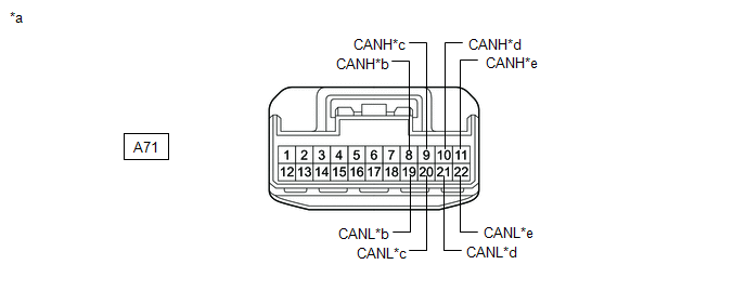
| *a | Front view of wire harness connector (to No. 2 Junction Connector) | *b | to No. 4 CAN Junction Connector |
| *c | to Brake Booster with Master Cylinder Assembly | *d | to Inverter with Converter Assembly |
| *e | to ECM | - | - |
Standard Resistance:
| Tester Connection | Condition | Specified Condition | Connected to |
|---|---|---|---|
| A71-8 (CANH) - A71-19 (CANL) | Cable disconnected from negative (-) auxiliary battery terminal | 108 to 132 Ω | No. 4 CAN junction connector |
| A71-9 (CANH) - A71-20 (CANL) | Cable disconnected from negative (-) auxiliary battery terminal | 200 Ω or higher | Brake booster with master cylinder assembly |
| A71-10 (CANH) - A71-21 (CANL) | Cable disconnected from negative (-) auxiliary battery terminal | 200 Ω or higher | Inverter with converter assembly |
| A71-11 (CANH) - A71-22 (CANL) | Cable disconnected from negative (-) auxiliary battery terminal | 108 to 132 Ω | ECM |
| Result | Proceed to |
|---|---|
| OK | A |
| NG (Line to ECM) | B |
| NG (Line to No. 4 CAN junction connector) | C |
| NG (Line to ECU or sensor) | D |
| A | .gif) | REPLACE NO. 2 JUNCTION CONNECTOR |
| C | | GO TO STEP 3 |
| D | | GO TO STEP 6 |
|
.gif)
| 2. | CHECK FOR SHORT IN CAN BUS LINES (NO. 2 JUNCTION CONNECTOR - ECM) |
(a) Disconnect the A26 ECM connector.
(b) Measure the resistance according to the value(s) in the table below.
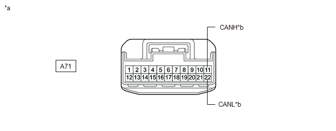
| *a | Front view of wire harness connector (to No. 2 Junction Connector) | *b | to ECM |
Standard Resistance:
| Tester Connection | Condition | Specified Condition |
|---|---|---|
| A71-11 (CANH) - A71-22 (CANL) | Cable disconnected from negative (-) auxiliary battery terminal | 1 MΩ or higher |
| OK | | REPLACE ECM |
| NG | | REPAIR OR REPLACE CAN MAIN BUS LINES OR CONNECTOR (NO. 2 JUNCTION CONNECTOR - ECM) |
| 3. | CHECK FOR SHORT IN CAN BUS LINES (NO. 4 CAN JUNCTION CONNECTOR) |
(a) Disconnect the G99 No. 4 CAN junction connector.
(b) Measure the resistance according to the value(s) in the table below.
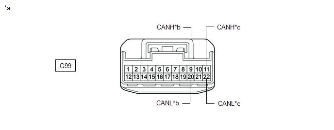
| *a | Front view of wire harness connector (to No. 4 CAN Junction Connector) | *b | to Hybrid Vehicle Control ECU |
| *c | to No. 2 Junction Connector | - | - |
Standard Resistance:
| Tester Connection | Condition | Specified Condition | Connected to |
|---|---|---|---|
| G99-9 (CANH) - G99-20 (CANL) | Cable disconnected from negative (-) auxiliary battery terminal | 200 Ω or higher | Hybrid vehicle control ECU |
| G99-11 (CANH) - G99-22 (CANL) | Cable disconnected from negative (-) auxiliary battery terminal | 1 MΩ or higher | No. 2 junction connector |
| Result | Proceed to |
|---|---|
| OK | A |
| NG (Line to No. 2 junction connector) | B |
| NG (Line to ECU or sensor) | C |
| B | | REPAIR OR REPLACE CAN MAIN BUS LINES OR CONNECTOR (NO. 4 CAN JUNCTION CONNECTOR - NO. 2 JUNCTION CONNECTOR) |
| C | | GO TO STEP 6 |
|
| 4. | CHECK FOR SHORT IN CAN BUS LINES (NO. 4 CAN JUNCTION CONNECTOR) |
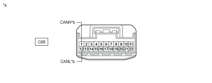
(a) Disconnect the G98 No. 4 CAN junction connector.
(b) Measure the resistance according to the value(s) in the table below.
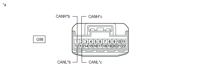
| *a | Front view of wire harness connector (to No. 4 CAN Junction Connector) | *b | to Central Gateway ECU (Network Gateway ECU) |
| *c | to Vehicle Approaching Speaker Controller | - | - |
Standard Resistance:
| Tester Connection | Condition | Specified Condition | Connected to |
|---|---|---|---|
| G98-1 (CANH) - G98-12 (CANL) | Cable disconnected from negative (-) auxiliary battery terminal | 108 to 132 Ω | Central gateway ECU (network gateway ECU) |
| G98-2 (CANH) - G98-13 (CANL) | Cable disconnected from negative (-) auxiliary battery terminal | 200 Ω or higher | Vehicle approaching speaker controller |
| Result | Proceed to |
|---|---|
| OK | A |
| NG (Line to central gateway ECU (network gateway ECU)) | B |
| NG (Line to ECU or sensor) | C |
| A | | REPLACE NO. 4 CAN JUNCTION CONNECTOR |
| C | | GO TO STEP 6 |
|
| 5. | CHECK FOR SHORT IN CAN BUS LINES (NO. 4 CAN JUNCTION CONNECTOR - CENTRAL GATEWAY ECU (NETWORK GATEWAY ECU)) |
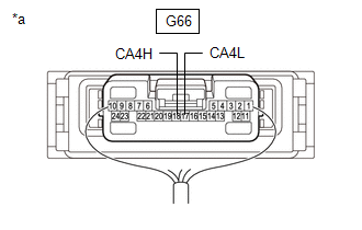
(a) Disconnect the G66 central gateway ECU (network gateway ECU) connector.
(b) Measure the resistance according to the value(s) in the table below.
| *a | Front view of wire harness connector (to No. 4 CAN Junction Connector) | *b | to Central Gateway ECU (Network Gateway ECU) |
Standard Resistance:
| Tester Connection | Condition | Specified Condition |
|---|---|---|
| G98-1 (CANH) - G98-12 (CANL) | Cable disconnected from negative (-) auxiliary battery terminal | 1 MΩ or higher |
| OK | | REPLACE CENTRAL GATEWAY ECU (NETWORK GATEWAY ECU) |
| NG | | REPAIR OR REPLACE CAN MAIN BUS LINES OR CONNECTOR (NO. 4 CAN JUNCTION CONNECTOR - CENTRAL GATEWAY ECU (NETWORK GATEWAY ECU)) |
| 6. | CHECK FOR SHORT IN CAN BUS LINES (ECU OR SENSOR) |
(a) Reconnect all wire harness connectors.
(b) Disconnect the connector that includes terminals CANH and CANL from the ECU or sensor to which the short circuited branch line is connected.
Click here
| (c) Measure the resistance according to the value(s) in the table below. Standard Resistance:
HINT:
|
|
| OK | | REPLACE ECU OR SENSOR |
| NG | | REPAIR OR REPLACE HARNESS OR CONNECTOR |
READ NEXT:
 Open in Bus 2 Main Bus Line
DESCRIPTION There may be an open circuit in one of the CAN main bus lines when the resistance between terminals 18 (CA4H) and 17 (CA4L) of the central gateway ECU (network gateway ECU) is 70 Ω or hig
Open in One Side of Bus 1 Branch Line
DESCRIPTION When the CAN bus main lines are normal (no open, short to ground, short to +B or short between lines) and there is an ECU or sensor on the "Communication Bus Check" screen that is indicate
Check Bus 1 Line for Short to GND
DESCRIPTION There may be a short circuit between one of the CAN bus lines and GND when there is no resistance between terminal 23 (CA1H) of the central gateway ECU (network gateway ECU) and terminal 4
SEE MORE:
Installation
INSTALLATION PROCEDURE 1. ALIGN FRONT WHEELS FACING STRAIGHT AHEAD 2. INSTALL STEERING COLUMN ASSEMBLY NOTICE: Make sure that the wire harness is not interfering with the steering column assembly. (a) Install the steering column assembly with the bolt and 2 nuts. Torque: 36 N·m {367 kgf·cm, 27 ft
Components
COMPONENTS ILLUSTRATION *1 INPUT SHAFT TYPE T OIL SEAL *2 HYBRID VEHICLE TRANSAXLE ASSEMBLY ● Non-reusable part MP grease
